
Blogs, Bevel Gear
What Causes Pitting on Bevel Gear Teeth?
Sep
Small pits on a bevel gear tooth are often blamed on poor material or low hardness. Those are possible causes, but they are rarely the only ones. Pitting usually develops when repeated contact stress acts on a local area that is carrying more load than expected. The contact pattern, mounting position, lubrication, tooth finish, heat treatment, and actual duty cycle all affect that stress.
This is especially important for spiral bevel, straight bevel, and hypoid gears. At Wenlio, these factors are typically reviewed together because a gear can meet its dimensional and hardness requirements yet still pit early if the assembled contact is too narrow or shifted toward an edge.
How Pitting Develops on Bevel Gear Teeth
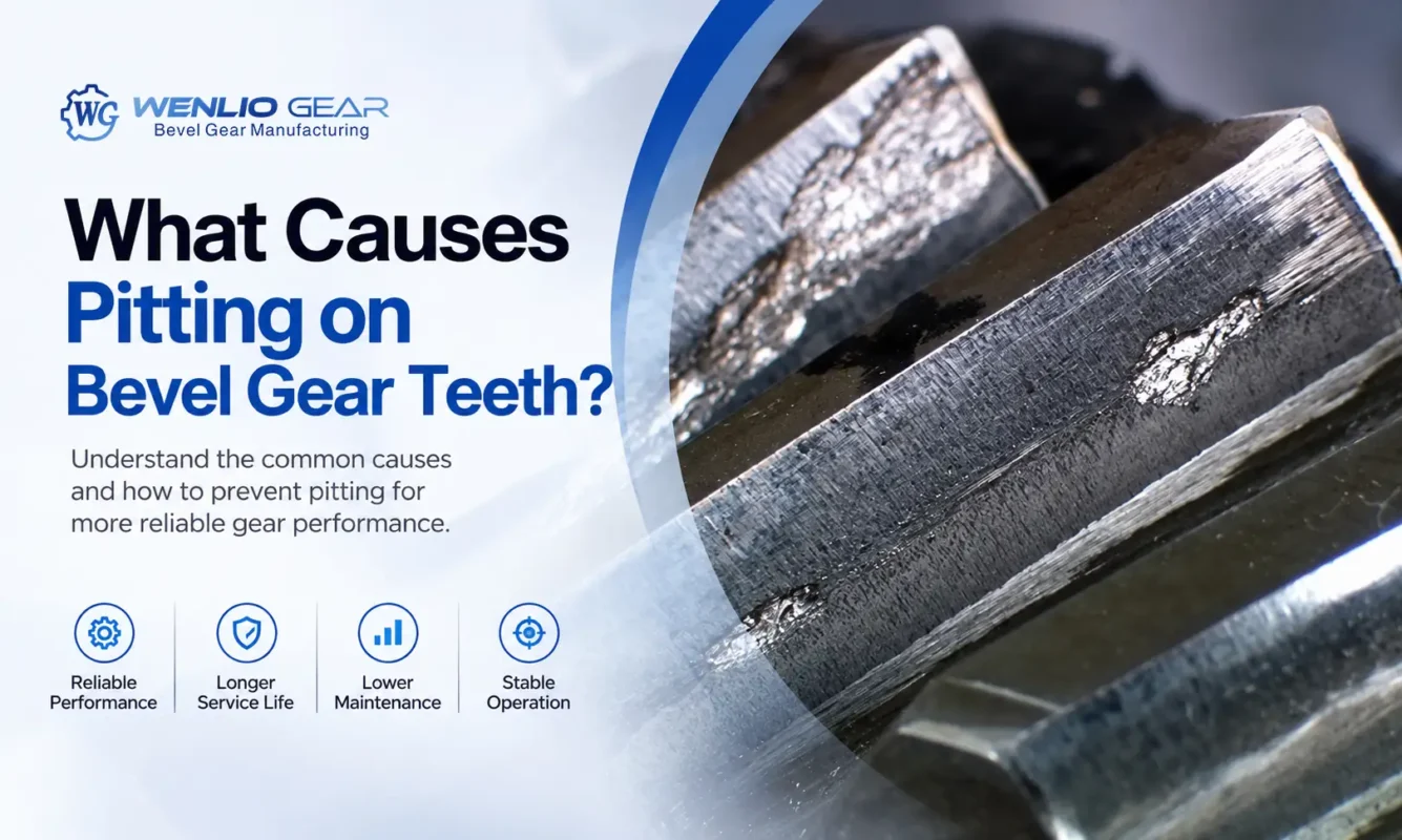
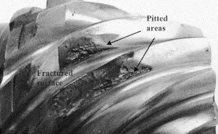
Pitting is a form of surface contact fatigue. During meshing, the same areas of a tooth pass through repeated contact cycles. If the local stress approaches or exceeds the fatigue capacity of the surface, small cracks may form at or just below it. As those cracks grow, fragments of material break away and leave visible cavities.
The position of the damage often says more than its mere presence. Pits concentrated near the heel, toe, root, or top land point toward a local contact problem. More evenly distributed damage may suggest a broader issue involving load, lubricant film, or surface fatigue strength.
-774x400.webp)
Why Tooth Contact Matters So Much
Bevel gear geometry changes along the pitch cone. In spiral bevel and hypoid sets, tooth curvature, spiral angle, mounting position, and mating geometry also shape the working contact area. The result is more sensitive to assembly conditions than the contact of a typical spur gear pair.
Under the intended setup, load is distributed within a controlled contact zone. If that zone becomes narrow or moves too close to the heel, toe, root, or top edge, a smaller surface must carry the same torque. Contact stress rises in that area even when the transmitted load has not changed.
A no-load marking test is useful, but shaft deflection, bearing movement, and housing deformation can shift the pattern under torque. Recurring pitting should therefore be assessed in the assembled transmission. For applications where backlash and contact condition are acceptance criteria, matched-set inspection of the bevel gear pair may provide more useful information than inspecting the two parts separately.
Common Causes of Pitting on Bevel Gear Teeth
Contact Pattern Shift
A shifted or undersized contact pattern is one of the clearest routes to local overload. For example, a pair may show acceptable tooth geometry during inspection, but contact may concentrate near the toe after assembly. That region then carries a greater share of the load and can pit earlier than the rest of the tooth.
When the damaged area closely follows an abnormal contact zone, dimensional checks on one gear are not enough. The mating gear, mounting distance, axial position, backlash, and support condition should be reviewed together.
Mounting Distance and Alignment
Bevel gears are sensitive to mounting position. A small change in mounting distance can move contact across the tooth surface. Bearing clearance, shaft runout, axial movement, and housing accuracy can have a similar effect.
Under load, shafts, bearings, and housings can deflect. A contact pattern that appears acceptable during a static check may move once torque is applied. If the loaded contact shifts toward an edge, local stress rises and surface fatigue can develop earlier.
Unsuitable Backlash
Backlash must suit the gear geometry, mounting arrangement, lubricant, and operating temperature. Too little backlash reduces the allowance for thermal growth and assembly variation. Too much can increase impact as the direction or level of load changes.
For bevel gears, backlash also changes with relative mounting position. It should therefore be checked together with contact pattern and mounting references rather than treated as an isolated value.
Load Above the Design Condition
The load used in a calculation may differ from the load seen in service. Sustained overload, frequent starts, shock loading, and restart after a jam can produce higher contact stress than the nominal power rating suggests.
An equipment upgrade can create the same problem if motor power or output demand increases while the original gear set remains in place. If severe pitting repeatedly develops in the same region, actual torque peaks and duty-cycle changes should be reviewed.
Insufficient or Contaminated Lubrication
Lubricant separates the mating surfaces with a protective film. If that film becomes too thin, microscopic high points on the teeth interact more directly. Friction and local stress increase, particularly on a rough surface or under heavy load.
Incorrect viscosity, excessive oil temperature, low oil level, poor delivery, or an unsuitable lubrication method can reduce film thickness. Hypoid gears need particular attention because their meshing action includes substantial sliding. The relationship between offset, sliding, tooth contact, and lubrication is explained further in Hypoid Gear Offset: How Does It Affect Performance?.
Surface Finish and Machining Quality
A tooth that appears smooth still has microscopic peaks and valleys. When roughness is high relative to lubricant film thickness, the peaks carry concentrated loads. This does not mean that the lowest possible roughness will solve every problem. Tooth geometry and contact position still control where the load acts.
Cutting, grinding, and lapping leave different surface textures. The finishing route should suit the geometry, load, speed, noise requirement, and lubrication. For a closer look at how roughness interacts with contact and lubrication, see Bevel Gear Surface Roughness and Why It Matters.
Material and Heat Treatment
Material and heat treatment set the surface’s resistance to repeated contact stress. For case-hardened gears, relevant checks include surface hardness, effective case depth, core properties, microstructure, and the condition of the surface after heat treatment.
A shallow case may not support the intended cyclic load. An unsuitable microstructure or surface defect can also reduce fatigue strength. Heat-treatment distortion adds another risk because it can change tooth geometry and move the contact pattern, even when hardness is within specification.
Material selection should therefore be considered together with heat treatment, load, distortion control, and tooth finishing. More detail is available in How to Choose Materials for Bevel Gears.
What Pitting Location Can Reveal
Damage near the heel or toe often suggests that the contact pattern has shifted lengthwise across the tooth. Pitting close to the root or top land may indicate that the contact position is too low or too high. A narrow damaged band usually deserves closer attention because it may point to concentrated loading.
These patterns provide useful clues, but they do not confirm the cause by themselves. Both mating tooth surfaces should be compared, and the contact pattern should be recorded before the mounting position or backlash is changed.
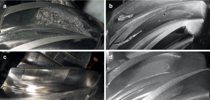
Pitting vs Micropitting vs Scuffing vs Spalling
These surface damage modes can sometimes look similar in field photographs, but their mechanisms are different.
| Damage Type | Typical Appearance | Commonly Associated Factors |
| Pitting | Visible pits and localized material loss | Repeated contact fatigue, high local stress |
| Micropitting | Gray or frosted appearance with very fine damage | Thin lubricant film, roughness, high contact stress |
| Scuffing | Scratches, scoring, or dragged surface marks | High sliding, temperature rise, lubricant breakdown |
| Spalling | Larger areas of material flaking away | More advanced fatigue-related surface damage |
A single photograph may not always be enough to identify the exact failure mode. Damage morphology, location, lubrication condition, material, hardness, and operating history should all be considered.
How to Reduce the Risk of Bevel Gear Pitting
Pitting prevention starts with a realistic duty cycle. Design inputs should reflect peak torque, operating speed, starts, reversals, impact loads, temperature, and expected service life. During production, tooth geometry, surface finish, and heat-treatment distortion need to be controlled.
Assembly and maintenance also affect surface life. Mounting distance, axial position, backlash, bearing condition, and contact pattern should be verified before operation. The specified lubricant viscosity, oil temperature, and cleanliness limits should then be maintained during service.
For matched gear sets, finishing processes may also be part of the contact-control strategy. Bevel gear lapping after cutting can help refine minor contact irregularities and support pair matching, although it cannot correct major geometry, mounting, or heat-treatment problems.
What to Check After Pitting Appears
Begin by recording which gear is affected, which teeth show damage, and where the pits appear. Compare several teeth rather than relying on one close-up image. The mating surface and contact pattern should also be inspected for edge contact or an unusually narrow contact zone.
Next, check mounting distance, backlash, bearings, runout, lubricant grade, oil level, temperature, and contamination. If these checks do not explain the damage, compare surface hardness, effective case depth, microstructure, tooth accuracy, and roughness with the drawing and production records. Actual torque peaks, impact events, and equipment modifications should also be reviewed.
If surface damage is accompanied by unusual running sound, the troubleshooting sequence in Spiral Bevel Gear Noise: What Should You Check First? can also help separate meshing, mounting, bearing, and lubrication issues.
FAQ
Can a Bevel Gear Continue Running After Light Pitting Appears?
That depends on the affected area, rate of progression, load, and consequence of failure. Critical drives should be assessed before continued operation. Monitoring alone is not a substitute for finding the cause.
Does Pitting Mean the Gear Hardness Is Too Low?
No. Low hardness may contribute, but pitting can also result from concentrated contact, incorrect mounting, poor lubrication, overload, or an unsuitable surface condition.
Are Spiral Bevel Gears More Likely to Pit Than Straight Bevel Gears?
Not necessarily. Neither type is naturally more prone to pitting. In practice, pitting is influenced more by load, material and heat treatment, gear accuracy, installation, and lubrication conditions.
Can Better Lubrication Eliminate Pitting?
Correct lubrication can reduce surface interaction and improve fatigue life, but it cannot correct edge contact, overload, heat-treatment defects, or an unstable mounting arrangement.
Can the Contact Pattern Identify the Cause?
It can show whether local load concentration is likely, especially when the damaged zone matches the contact area. A complete diagnosis still needs assembly, lubrication, material, and operating data.
Conclusion
Bevel gear pitting begins with repeated contact fatigue, but the visible pits are usually the end result of several interacting conditions. Their location can help narrow the search. Concentrated damage calls for close attention to contact pattern and mounting, while broader damage may lead the investigation toward load, lubrication, or surface fatigue strength.
If you are investigating pitting in a bevel gear application, Contact us to send your drawings, photographs of both mating tooth surfaces, contact pattern images, and basic operating data. These details provide a practical starting point for reviewing the gear pair and the surrounding transmission.
