
Blogs, Bevel Gear
What to Check in Construction Equipment Bevel Gear Sets
Oct
Bevel gear drives don’t get an easy life in construction equipment. They handle high torque, shock loads, constant starts and stops, and plenty of dust and grime along the way. When the gear and pinion aren’t matched properly, or the installation or heat treatment is off, the result is usually the same: uneven wear, a shifted contact pattern, extra noise, or premature failure.
That’s why it pays to look past tooth count, dimensions, and price. In a custom or replacement job, the operating load, mating gear data, material and heat treatment, mounting dimensions, and inspection requirements all play a part. At Wenlio, we always recommend reviewing the gear set as a complete package, together with how it will actually be assembled, instead of treating each part on its own.
What Should Buyers Check Before Bevel Gear Ordering?
Before you order a bevel gear set for construction equipment, make sure you can answer at least the points below:
- Application position and operating load
- Complete data for both the gear and pinion
- Tooth counts, ratio, spiral hand, and shaft angle
- Material and heat treatment requirements
- Gear accuracy and runout limits
- Mounting distance
- Backlash
- Contact pattern
- Bearing, housing, and assembly conditions
- Inspection standards and required reports
Leave any of these gaps open and you risk getting parts that don’t match the real assembly.
This matters even more for replacement gears. Just matching the outside diameter, tooth count, and mounting holes of an old part doesn’t mean the new set will mesh correctly once it’s assembled.
Why Gear Pairing Matters in Construction Equipment
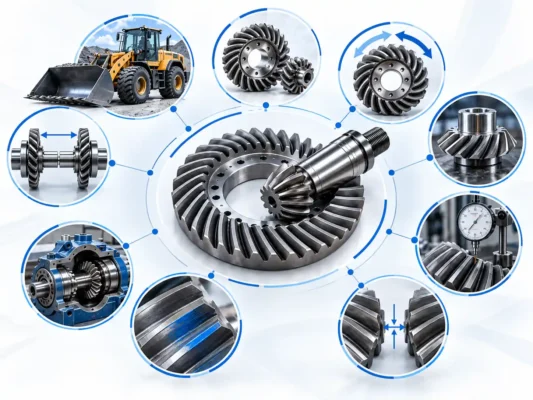
A bevel gear rarely works alone; it’s one half of a matched gear and pinion pair.
You can inspect the two parts separately all you want, but in most bevel gear applications what really counts is how they touch each other after assembly.
Construction machines also throw large, fast load changes at the drivetrain, starting, steering, digging, lifting, reversing. If the contact area sits in the wrong place, all that load concentrates on a small section of the tooth and pushes local contact stress way up.
So it’s worth asking more than
“Does each gear meet the dimensional requirements?”
You should also be asking
“Will the gear and pinion mesh correctly after assembly?”
Confirm Where the Bevel Gear Set Will Be Used
Before you even talk about material or price, settle where the gear set will actually work.
Typical spots include:
- Excavators
- Wheel loaders
- Cranes
- Final drives
- Swing drives
- Axles
- Differentials
- Other heavy-duty transmission systems
Speed, torque, shock load, and duty cycle can be very different from one location to the next.
Anything you can tell the supplier here helps:
| Information | Why It Matters |
| Equipment type | Defines the actual operating environment |
| Gear location | Shows where the gear set sits in the drivetrain |
| Input speed | Affects operating behavior and lubrication needs |
| Torque or load | Supports tooth-flank and tooth-root load assessment |
| Duty cycle | Shows whether operation is continuous or intermittent |
| Rotation direction | Confirms the actual working direction |
| Lubrication | Defines the available lubrication conditions |
| Working environment | Covers dust, temperature, shock, and similar factors |
Review the Complete Gear Set
The first thing to confirm for a bevel gear set is that the gear and pinion come from the same design system.
Then run through the basic parameters:
- Gear tooth count
- Pinion tooth count
- Gear ratio
- Spiral hand
- Shaft angle
- Pitch cone geometry
- Bore and mounting details
- Mating gear data
Two bevel gears can look the same size on paper and still not interchange. If the tooth geometry, mounting position, or pairing data differ, they simply won’t work as a set.
On a replacement project, send both mating parts whenever you can, not just the damaged one.
A badly worn gear skews measurements, and whatever assembly error caused the damage gets copied straight into the new part.
Specify Material and Heat Treatment
Gears in construction equipment usually need a hard, wear-resistant surface and a tough core underneath.
Don’t just ask
“What material is used?”
You also need to pin down:
- Material grade
- Heat treatment method
- Surface hardness
- Effective case depth
- Core hardness
- Heat treatment specification
Case-hardened alloy steel shows up a lot in high-load applications, but there’s no single material or heat treatment that fits every bevel gear.
The right choice follows
the drawing, the operating load, and the application, not some generic notion of a standard heavy-duty gear material.
If you have the original drawing, put its material, hardness, and case-depth requirements straight into the RFQ.
If the drawing is incomplete, sit down with the old parts and the actual operating conditions before you decide.
Define Gear Geometry and Accuracy
Outside diameter, bore size, and tooth count alone don’t define a bevel gear.
You also need to review:
- Tooth flank geometry
- Tooth spacing
- Runout
- Pitch accuracy
- Tooth surface condition
- Gear accuracy grade
If noise, service life, or speed targets are demanding, expect to need tighter design controls and more detailed inspection.
The RFQ should state the acceptance basis, for example:
- Drawing requirements
- ISO requirements
- AGMA requirements
- Customer-specific standards
Try to avoid vague wording like
“High precision required.”
“High precision” isn’t a measurable manufacturing or acceptance standard.
Use Contact Pattern to Verify the Gear Pair
The contact pattern shows exactly where the gear and pinion touch under defined test or assembly conditions.
It should follow the original design intent and stay away from the extreme edges of the tooth flank.
A poor contact pattern can point to:
- Mounting distance
- Backlash
- Gear geometry
- Pinion position
- Shaft angle
- Bearing position
- Housing accuracy
Don’t accept a bevel gear set just because both parts can “turn together.”
The more meaningful check is
whether the assembled contact pattern meets the design requirement for that particular pair.
Target patterns differ from one bevel gear design to the next, so don’t rely on a single generic pattern chart for every set.
Check Backlash and Mounting Distance Together
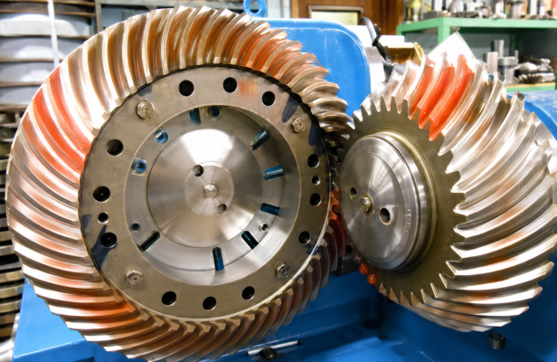
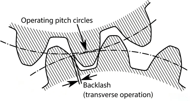
Backlash is simply the working clearance between mating tooth flanks.
The right amount of backlash leaves room for lubrication, thermal expansion, and normal running.
But here’s the thing:
normal backlash on its own doesn’t prove the set is installed correctly.
The actual mesh also hinges on mounting distance.
Mounting distance fixes the gear’s position relative to the design reference. If the axial position of the gear or pinion shifts, the contact pattern moves with it.
Before production or final assembly, confirm all three together:
- Mounting distance
- Backlash
- Contact pattern
Treat them as one package, not three separate checks.
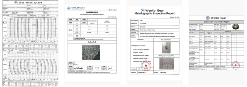
Agree on Inspection Documents Before Production
Agree on inspection requirements before production starts, not after the parts are already finished.
Depending on the project, the documents you need might include:
Material Certificate
States the material grade and the batch it came from.
Hardness Report
Records the surface hardness or whatever other hardness values were specified.
Case Depth Report
Shows the effective hardened case depth for surface-hardened gears.
Dimensional Inspection
Captures the key mounting dimensions, bores, faces, and other drawing dimensions.
Gear Geometry Inspection
Covers tooth geometry, runout, and the other specified gear parameters.
Contact Pattern Check
Verifies how the mating gear and pinion contact under defined conditions.
You won’t need every one of these on every project.
Pick the inspection scope according to
how critical the part is, what stage the project is at, and what the end customer requires.
Investigate Why the Original Gears Failed
A common trap in replacement projects is assuming
the old gear failed, so an identical-looking new one will fix everything.
If the real culprit was assembly, lubrication, or bearings, swapping in a new gear won’t remove the root cause.
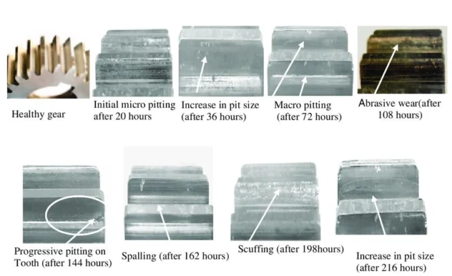
Look for:
- Tooth pitting
- Scuffing
- Tooth breakage
- Uneven wear
- Edge contact
- Abnormal polishing
- Bearing condition
- Lubrication condition
Wear marks on the old parts tell your engineer a lot about how the set was actually meshing.
Keep the old gears and send clear photos of the tooth flanks. Don’t grind or heavily clean them before the evaluation.
Bevel Gear Set RFQ Checklist
Before you send an RFQ, have this information ready:
| Item | Information to Provide |
| Equipment | Equipment type and model |
| Application | Final drive, axle, swing drive, or other location |
| Drawing | Drawings for both the gear and pinion |
| Sample | Original parts or clear photos |
| Tooth count | Tooth counts for the gear and pinion |
| Ratio | Gear ratio |
| Shaft angle | Required shaft angle |
| Mounting distance | Required mounting distance |
| Backlash | Design or assembly requirement |
| Material | Material grade |
| Heat treatment | Heat treatment requirement |
| Hardness | Specified hardness |
| Case depth | Effective hardened case depth |
| Accuracy | Drawing-specified accuracy grade or tolerance |
| Inspection | Inspection and reporting requirements |
| Quantity | Prototype, repeat order, or production quantity |
| Operating condition | Speed, load, and duty cycle |
| Failure information | Wear or failure observed on the original parts |
The more complete your input, the easier it is for us to spot technical risks before we quote.
Avoid Common Purchasing Mistakes
Providing only the damaged gear
When you order a matched bevel gear set, send data for the mating part as well.
Checking only overall dimensions
Outside diameter, bore, and tooth count matching doesn’t prove the tooth geometry and pairing are right.
Ignoring mounting data
Mounting distance, backlash, and shaft position can all shift the final contact pattern.
Focusing only on hardness
Hardness matters, sure, but only when you look at it alongside material grade, case depth, core properties, and the whole heat treatment process.
Requesting inspection documents only before shipment
Mention any special reporting requirements during the RFQ or drawing approval stage, not at the last minute.
How Wenlio Manages Custom Bevel Gear Projects
A solid custom project starts with technical clarification, not with rushing to copy a sample.
Here’s the process we usually recommend:
Requirement Collection
We gather the drawings, samples, equipment data, operating conditions, and mating gear information.
Technical Clarification
We confirm the material, heat treatment, gear geometry, mounting requirements, and inspection standards.
Manufacturing Planning
We map out the machining and inspection route for the part.
Prototype and Validation
Prototype parts confirm the key dimensions, mesh condition, and assembly feedback.
Production and Quality Control
We produce and inspect the rest of the batch to the approved technical requirements.
For high-load bevel gear sets, settling pairing and assembly requirements early cuts the risk of rework and technical disputes later.
FAQ
Must Construction Equipment Bevel Gears Be Purchased as a Set?
Not necessarily. But when the pairing has a strong influence on the contact pattern and mounting, buying and checking them as a set usually gives you much better control over the final assembly.
Can a Gear Be Remanufactured from an Old Sample Without a Drawing?
It can be evaluated, but we’d also need the mating gear, equipment model, mounting dimensions, and the wear condition. A severely worn sample shouldn’t be treated as the original design geometry.
Why Can a Dimensionally Correct Gear Still Show a Poor Contact Pattern?
Plenty of things can do it: mounting distance, backlash, bearing position, housing dimensions, shaft misalignment, gear geometry. It often isn’t one single gear dimension at fault.
Which Material Is Best for Construction Equipment Bevel Gears?
There’s no one material that fits everything. You choose the material and heat treatment around the load, speed, target life, shock conditions, and the original design. Case-hardening alloy steels are common in high-load service, but the exact grade has to come from the project requirements.
What Information Is Needed for a Bevel Gear Set RFQ?
Send the drawings for the gear and pinion, the equipment application, tooth counts, ratio, material, heat treatment, mounting data, inspection requirements, quantity, and operating conditions. No drawings? Clear sample photos plus the key assembly data are enough to start with.
Conclusion
For construction equipment, the goal isn’t to find a gear that’s roughly the right size. The set has to suit the real operating conditions, match as a pair, and give you the intended contact pattern once assembled.
If you have a custom or replacement project, send Wenlio the drawings, photos of the old parts, mating gear data, equipment model, and operating conditions. The better the input, the earlier we can flag risks before quotation and production, and the clearer the manufacturing and inspection requirements become. Contact us to discuss your bevel gear requirements.
