
Blogs, Bevel Gear
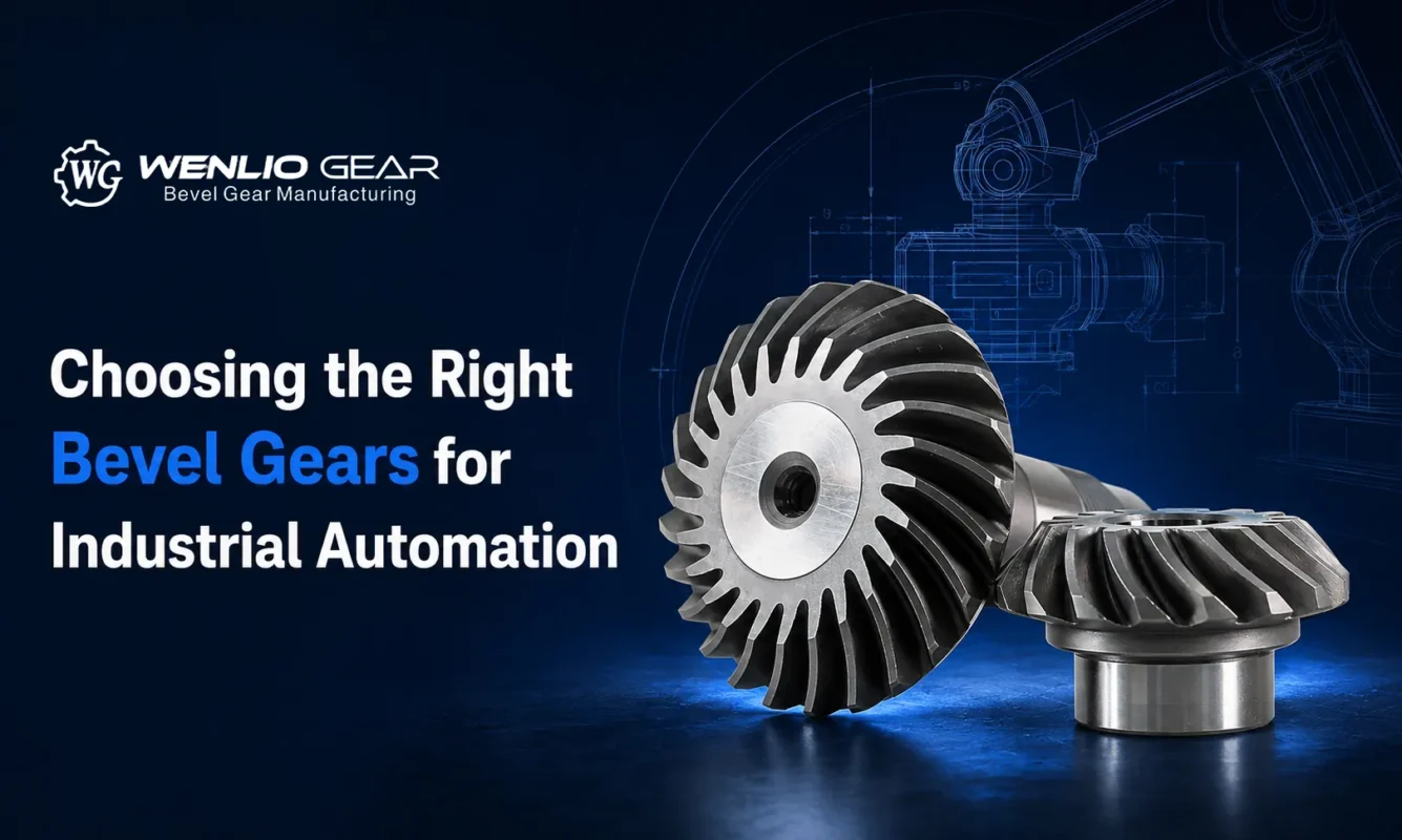
Choosing the Right Bevel Gears for Industrial Automation
Aug
Introduction
Industrial automation equipment often uses bevel gears to redirect power within limited spaces, including robot joints, packaging machines, conveyors, machine-tool angle drives, and positioning units. When selecting bevel gears for industrial automation, engineers and buyers should evaluate speed, torque, start-stop frequency, rotation direction, backlash, noise, installation space, and bearing conditions, because one tooth form cannot suit every application.
At Wenlio, we review custom bevel gears as part of the complete transmission system rather than selecting them only by tooth count, module, or outside diameter. The drawing, mating relationship, operating conditions, and inspection needs should be considered together before the manufacturing route is confirmed.
Quick Answer
Bevel gears for industrial automation should be selected according to speed, torque, duty cycle, reversing frequency, backlash, noise, and shaft layout. Straight bevel gears may suit simpler low-speed drives, while spiral bevel gears may suit smoother or higher-speed transmission. Miter, Zerol, or hypoid designs may be considered when ratio, thrust, or shaft offset creates additional requirements.
Why Are Bevel Gears Used in Industrial Automation?
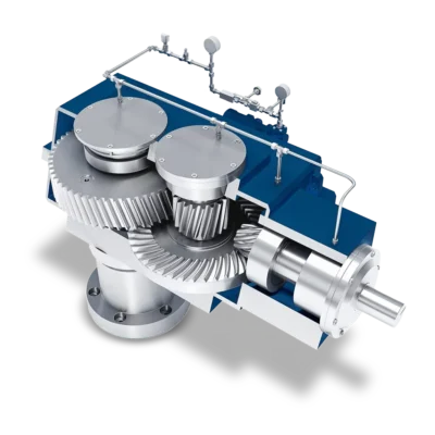
The main function of a bevel gear is to transmit torque between shafts positioned in different directions. Many automation systems require a compact right-angle drive but cannot accommodate a longer belt, chain, or parallel-shaft gear arrangement.
Robot Joints and Compact Actuators
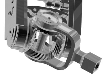
Robot joints, gripping mechanisms, and compact actuators often have limited installation space. In addition to overall dimensions, these applications may need to consider:
- Positioning repeatability;
- Forward and reverse operation;
- Backlash;
- Noise and vibration;
- The ability of the bearings to support axial thrust.
Conveyors, Packaging Machines, and Machine Tools
Conveyor and packaging equipment may run continuously or start and stop frequently. Machine-tool angle heads and positioning mechanisms may place greater emphasis on rigidity, runout, and transmission stability.
As a result, two machines with the same gear ratio may still require very different bevel gear designs and inspection plans.
What Should Be Confirmed Before Selecting Bevel Gears for Industrial Automation?
Speed, Torque, and Duty Cycle
Motor power alone is usually not enough to determine whether a bevel gear is suitable. The project should also define:
- Input and output speeds;
- Normal and peak torque;
- Continuous or intermittent operation;
- Number of start-stop cycles per hour;
- Possible shock loading;
- Daily operating time.
Continuous high-speed operation and low-speed intermittent operation place different demands on tooth form, material, heat treatment, lubrication, and accuracy.
One-Way Operation or Frequent Reversing
Frequent reversing causes the gear pair to carry load alternately on opposite tooth flanks. The project should therefore consider backlash variation, tooth contact, bearing support, and reversing impact rather than evaluating performance in only one direction.
Backlash, Positioning, and Noise Requirements
Low backlash does not mean zero backlash. Excessive backlash may affect reversing response and positioning, while insufficient backlash may cause tight meshing, higher operating temperatures, or poor lubrication conditions.
Buyers should clarify whether the equipment requires:
- General power transmission;
- Controlled backlash;
- Repeatable positioning;
- Low-noise operation;
- High-precision motion control.
Backlash should therefore be defined according to the actual assembly and motion requirements rather than reduced without a clear target. The relationship between backlash, mounting position, and tooth contact is explained further in our guide to bevel gear backlash and contact pattern checks.
Which Bevel Gear Types Suit Different Automation Projects?
| Gear type | More suitable project conditions | Points to consider |
| Straight bevel gears | Low- to medium-speed, structurally simple, cost-sensitive drives | Tooth engagement is more direct, and noise may become more noticeable at higher speeds |
| Spiral bevel gears | Equipment requiring smoother operation, lower noise, or higher speed | Manufacturing and pair control are more complex, and axial thrust must be considered |
| Zerol bevel gears | Projects that require curved teeth while also needing careful control of thrust characteristics | Actual force direction and manufacturing requirements still depend on the specific design |
| Miter gears | Right-angle drives requiring a 1:1 speed ratio | “Miter” describes the 1:1 ratio relationship and does not define one specific tooth form |
| Hypoid gears | Compact layouts requiring offset input and output shafts | Greater sliding requires suitable lubrication and careful contact adjustment |
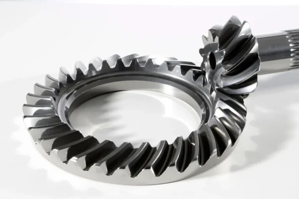
Straight and spiral bevel gears should not be viewed simply as lower-grade and higher-grade options. Straight bevel gears may be more practical for simple, low-speed mechanisms. Spiral bevel gears provide progressive engagement that may suit smoother-running applications, but they also require more careful manufacturing, installation, and inspection.
For a more detailed comparison, see Straight Bevel Gear vs Spiral Bevel Gear.
Are Spiral Bevel Gears Always Better for Automation Equipment?
Not necessarily.
The curved teeth of spiral bevel gears enter mesh progressively, which can support more continuous load transfer. However, they also introduce more complex tooth-surface geometry, axial thrust, mounting-distance requirements, and matched-pair control.
Spiral bevel gears should not be selected only because they may run more smoothly when:
- The equipment operates at a relatively low speed and has no strict noise requirement;
- The existing bearings cannot support additional axial thrust;
- The new gear must continue to mesh with an existing straight bevel gear;
- The housing and installation space cannot be changed;
- Only one worn sample is available and mating-gear data is missing;
- The project budget does not support more complex manufacturing and inspection.
The correct choice should begin with the operating conditions rather than the appearance of the tooth form.
What Information Should Buyers Provide Before Requesting a Quote?
| Information to provide | Why it matters |
| Equipment and application position | Clarifies the gear’s function within the system |
| Input and output speeds | Supports evaluation of operating speed and ratio |
| Normal and peak torque | Defines regular loading and possible overload conditions |
| Duty cycle | Distinguishes continuous, intermittent, and frequent start-stop operation |
| Direction of rotation | Identifies one-way or frequent reversing operation |
| Shaft angle and shaft position | Confirms an intersecting-shaft or offset-shaft layout |
| Backlash and noise requirements | Defines manufacturing and matched-pair priorities |
| Available installation space | Limits outside diameter, face width, and bearing arrangement |
| Drawing, 3D model, or sample | Supports geometry and manufacturability review |
| Quantity and inspection requirements | Helps plan prototype and production routes |
When only an old gear sample is available, buyers should also provide photographs of the mating gear, housing position, assembly relationship, and visible wear. Copying one worn component may not restore the original tooth-contact relationship.
What Should Be Inspected on Automation Bevel Gears?
The inspection scope should reflect the project risks rather than simply include as many inspection items as possible. Common inspection items may include:
- Critical installation dimensions;
- Tooth thickness and runout;
- Tooth-flank geometry;
- Backlash;
- Contact pattern;
- Material and heat treatment;
- Matched-pair identification;
- Prototype and production records.
High-speed, low-noise, reversing, or positioning-sensitive applications often require closer tooth-flank, mating, and assembly checks, while low-speed drives may focus on critical dimensions, tooth thickness, runout, and basic contact condition. Confirm the inspection scope during quotation and drawing review, since project conditions should define the final bevel gear inspection plan.
How Does Wenlio Review an Automation Bevel Gear Project?
Wenlio normally begins an initial project review with the following steps:
- Confirm the equipment function, shaft layout, and available installation space;
- Review speed, torque, duty cycle, and direction of rotation;
- Confirm the bevel gear type, ratio, and mating relationship;
- Plan the material, heat treatment, manufacturing, and inspection route;
- Approve the sample and inspection results before moving into batch production.
For new development projects, visit the Custom Gears page to learn more about made-to-drawing and sample-based manufacturing.
FAQ
Do All Industrial Automation Systems Need Low-Backlash Bevel Gears?
No. Low backlash is more relevant to reversing, positioning, and motion-control applications. General continuous power transmission may only require backlash that supports proper assembly and operation.
Can Straight Bevel Gears Be Used in Automation Equipment?
Yes. Straight bevel gears may be a practical option for simple mechanisms operating at low to medium speeds, moderate loads, and without strict noise requirements.
Are Spiral Bevel Gears Suitable for Frequent Reversing?
They may be suitable, but the project should confirm loading in both directions, backlash, tooth contact, axial thrust, and bearing support. Tooth form alone is not enough to determine suitability.
What Is the Difference Between Miter Gears and Other Bevel Gears?
Miter gears normally refer to a mating bevel gear pair with equal tooth counts and a 1:1 ratio. They may use straight or curved teeth. The defining feature is equal-speed directional transmission rather than one specific tooth geometry.
Can Wenlio Quote a Project Without a Complete Drawing?
An initial review may begin with a sample, clear photographs, critical dimensions, mating information, and application conditions. However, if the original part is worn, the mating gear and assembly relationship may also need to be reviewed before reliable manufacturing data can be established.
Conclusion
Choosing bevel gears for industrial automation involves more than comparing straight, spiral, Zerol, miter, or hypoid gear types. The project should also consider speed, torque, duty cycle, reversing motion, backlash, noise, shaft layout, bearing support, lubrication, and inspection requirements.
For a new automation project or replacement gear review, provide the drawing, sample photographs, mating information, installation layout, and actual operating conditions. You can contact Wenlio to begin a technical review based on the available project information.
