
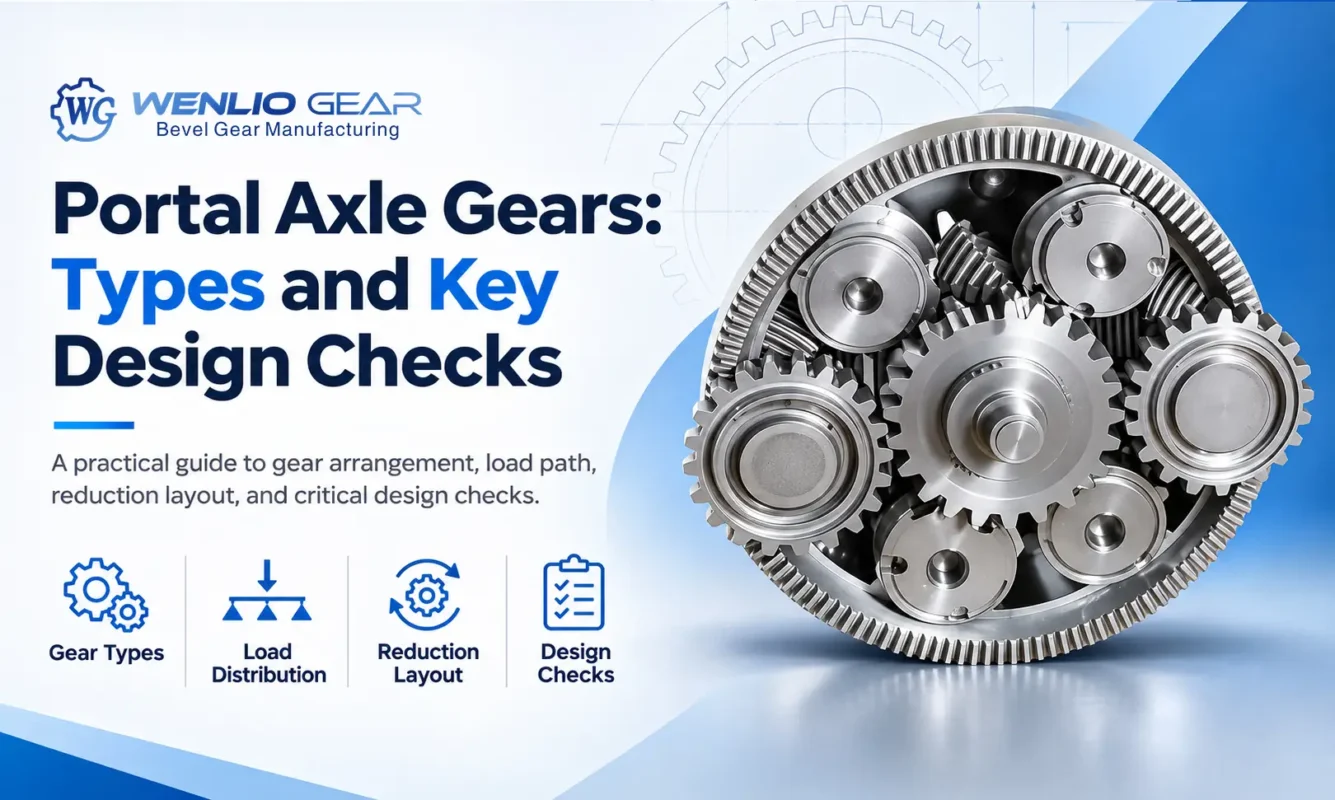
Portal axle gears are used in wheel-end drive systems where a vehicle needs extra ground clearance or an additional reduction stage near the wheel. The gear arrangement affects the axle layout, torque transmission and operating conditions. At Wenlio, we manufacture custom precision gears for OEM transmission applications, including bevel, spur and helical gears. This guide explains the gear types used in portal axle systems and the key design checks engineers should consider before manufacturing.
How Does a Portal Axle Work?
A portal axle uses a gear reduction mechanism at or near each wheel hub. Unlike a conventional axle, where the axle shaft and wheel centerline are generally aligned, a portal axle introduces a vertical offset between them.
This offset raises the axle housing relative to the wheel centers, improving ground clearance beneath the vehicle. The wheel-end gear mechanism may also provide additional reduction.
A typical power transmission path includes:
- The transmission delivers power to the drive axle.
- The final drive and differential distribute torque to the axle shafts.
- The axle shafts transfer power to the wheel-end gear mechanisms.
- The portal gear trains drive the wheel hubs.
- The wheel hubs transmit torque to the wheels.
The central final-drive gears and wheel-end portal gears are separate transmission stages. Their designs should be evaluated according to their respective positions and operating requirements.
Gear Types Used in Portal Axle Systems
The gear arrangement depends on the required reduction ratio, shaft position, installation space, torque capacity and noise requirements.
Spur Gears
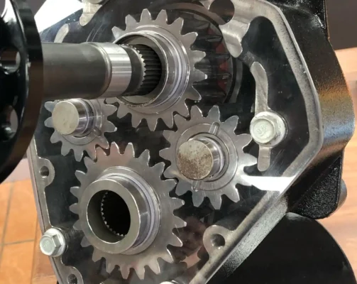
Spur gears have straight teeth and transmit power between parallel shafts. They are a practical option for relatively simple wheel-end reduction arrangements.
A typical gear train may contain an input gear, an output gear and one or more idler gears. Idlers help establish the required shaft positions and rotation direction without changing the overall ratio determined by the input and output gears.
Important design parameters include tooth count, module, pressure angle, center distance, backlash and face width. Tooth-root bending strength and tooth-surface contact stress should also be evaluated.
Helical Gears
Helical gears have angled teeth that engage progressively during rotation. This engagement can provide smoother meshing than spur gears under comparable design conditions.
They may be considered when noise, vibration and load distribution are important. However, helical gears generate axial thrust, which places additional requirements on bearings, shafts and housing support.
The helix angle, axial load, bearing capacity, shaft deflection and lubrication conditions should be checked together.
The choice between spur and helical gears depends on the complete transmission layout. For a closer comparison, see our guide to spur and helical gear selection.
Bevel and Hypoid Gears
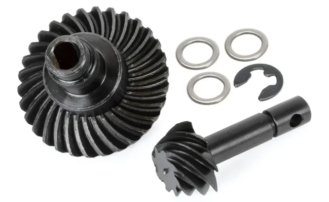
Bevel gears transmit power between intersecting shafts, while hypoid gears transmit power between offset, non-intersecting shafts.
Depending on the axle architecture, these gears may be used in the central final-drive section. They should not automatically be treated as the wheel-end portal reduction gears.
For bevel and hypoid gear sets, engineers should check shaft angle, pinion offset, mounting distance, spiral direction, backlash and tooth contact pattern. These parameters affect how the mating gears engage after assembly.
Learn more about bevel gear working principles and their different applications.
Planetary Gears
Some compact wheel-end drives use planetary gear sets to provide reduction around a common axis.
Their design requires attention to planet load sharing, carrier stiffness, gear alignment and bearing support. However, planetary gears are not used in every portal axle. The actual gear arrangement must be confirmed from the transmission design.
Key Design Checks for Portal Axle Gears
Selecting a suitable gear type is only the starting point. The complete gear system must be evaluated against its actual operating conditions.
Torque, Speed and Duty Cycle
Portal axle gears may experience continuous torque, acceleration loads and shock loads, particularly in off-road applications.
Engineers should establish:
- Continuous and peak input torque
- Operating speed
- Wheel load and vehicle weight
- Shock and impact loading
- Duty cycle and operating frequency
- Expected service life
These operating conditions provide the basis for gear sizing and strength calculations.
Gear Ratio and Portal Offset
The reduction ratio determines the relationship between input and output speed. A reduction stage lowers wheel-end speed and increases available output torque, subject to transmission losses.
Portal offset also affects gear positioning, center distance, housing dimensions and bearing locations.
Engineers should confirm the required gear ratio and installation geometry together. A gear train may meet the ratio requirement but still cause interference or leave insufficient space for bearings and seals.
Tooth Bending Strength and Contact Stress
Gear teeth experience repeated loading during operation. Tooth-root bending stress is associated with fatigue and possible tooth breakage, while excessive contact stress may contribute to surface damage such as pitting.
Calculations should consider torque, tooth geometry, face width, material properties, heat treatment and load distribution. The selected method must match the actual gear type and design conditions.
These calculations support design evaluation but do not replace prototype testing or validation of the complete axle assembly.
Shaft Alignment, Bearings and Backlash
Shaft deflection, bearing clearance and housing deformation can change the relative position of mating gears under load.
Even a gear manufactured according to its drawing may show uneven contact if the assembly cannot maintain the required alignment.
Important checks include:
- Shaft concentricity and runout
- Bearing position and support stiffness
- Gear mounting references
- Housing rigidity
- Center distance and alignment tolerances
- Backlash measurement and acceptance range
Excessive backlash may cause impact and noise, while insufficient backlash can result in tight meshing under changing temperatures and operating conditions.
For bevel gear assemblies, mounting distance should also be reviewed because it influences the installed relationship between mating gears.
Tooth Contact Pattern
For bevel and hypoid gear sets, contact-pattern inspection helps evaluate how the mating teeth engage.
A shifted or concentrated contact area may indicate incorrect mounting, alignment problems or an unsuitable mating condition. The inspection should consider the gear pair rather than relying only on individual dimensional measurements.
See our article on bevel gear contact pattern for further details.
Material, Heat Treatment and Lubrication
Material selection should match the expected load, wear and fatigue requirements. Depending on the design, gears may require carburizing, nitriding, induction hardening or another specified heat-treatment process.
Important factors include surface hardness, core properties, effective case depth and heat-treatment distortion.
Lubrication must also suit the gear speed, load and operating temperature. Oil viscosity, supply, sealing and contamination control should be considered during the design stage.
Poor lubrication can increase friction, surface wear and operating temperature, particularly under heavy loads.
Common Problems in Portal Axle Gear Systems
Gear problems may result from the interaction of design, manufacturing, assembly and operating conditions.
| Common problem | Possible factors to investigate |
| Tooth-root cracking or breakage | Excessive bending stress, shock loading or fatigue |
| Gear pitting | High contact stress, material condition or lubrication |
| Uneven tooth wear | Shaft misalignment, bearing clearance or load distribution |
| Excessive backlash | Incorrect dimensions, wear or assembly adjustment |
| Abnormal noise and vibration | Gear accuracy, contact conditions, bearings or mounting |
| Premature surface damage | Insufficient lubrication or contamination |
These symptoms do not have a single universal cause. A proper investigation should examine the gear pair, shafts, bearings, housing and lubrication system together.
Information Needed for Custom Portal Axle Gears
When sourcing custom portal axle gears, complete technical information helps the manufacturer evaluate feasibility and define the production requirements.
Buyers should prepare the following information where available:
| Information | Recommended details |
| Drawings or 3D models | PDF, DWG, STEP or IGES |
| Gear parameters | Tooth count, module, pressure angle, helix angle and ratio |
| Assembly details | Shaft positions, center distance, portal offset and mating gear data |
| Operating conditions | Torque, speed, load and duty cycle |
| Material and heat treatment | Material grade, hardness and treatment specifications |
| Inspection requirements | Gear accuracy, backlash and dimensional reports |
| Order information | Prototype quantity and estimated annual demand |
If drawings are unavailable, physical samples, photographs, mating components and application details can provide a starting point for technical review. Worn samples should be evaluated carefully because their current dimensions may not represent the original design.
Custom Gear Manufacturing Support from Wenlio
As a custom gear supplier, Wenlio provides manufacturing support for custom bevel gears, spur gears, helical gears, worm gears and gear shafts.
For portal axle-related projects, the manufacturing route depends on the confirmed gear design, material, accuracy requirements, production quantity and inspection scope.
Our gear manufacturing processes cover different machining and finishing requirements. Technical review can also include drawing clarification, material and heat-treatment requirements, manufacturing feasibility and inspection planning.
For quality requirements, our custom gear quality control and inspection process covers dimensional checks, gear-tooth inspection and other agreed project requirements.
The objective is to establish clear technical requirements before production and support consistent results from prototype approval to repeat orders.

FAQ
What Is the Main Purpose of a Portal Axle?
A portal axle uses a wheel-end gear arrangement to offset the wheel center from the axle shaft. This can increase ground clearance beneath the axle housing and provide additional reduction.
Which Gear Types Are Used in Portal Axle Systems?
Spur gear trains are used in some portal reduction designs. Helical or planetary gears may also be considered depending on the layout. Bevel and hypoid gears may be used in the central final drive.
Do Portal Axle Gears Increase Wheel Torque?
A reduction stage lowers output speed and increases torque, depending on the gear ratio and transmission efficiency.
What Causes Noise in Portal Axle Gear Systems?
Possible causes include incorrect backlash, poor tooth contact, gear accuracy errors, shaft misalignment, bearing problems and housing vibration.
Can Portal Axle Gears Be Manufactured From Samples?
Yes. A manufacturer can review physical samples, but worn parts may not retain the original tooth geometry. Drawings, mating components and operating information help confirm the design before production.
Conclusion
Portal axle performance depends on more than gear type. Load, ratio, alignment, backlash, material, lubrication and assembly conditions all influence how the system operates.
Before manufacturing, engineers and buyers should confirm the gear arrangement, operating requirements and inspection criteria. If you are sourcing custom portal axle gears, Contact Wenlio with your drawings, samples or project details for a manufacturing review.
