
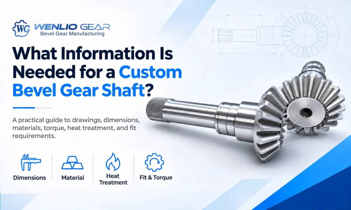
A custom bevel gear shaft must be specified as part of a working assembly, not simply as a gear profile attached to a shaft. Tooth geometry, bearing seats, mounting references and mating gear data all affect whether the component can be manufactured and installed correctly. Buyers preparing an RFQ should provide enough information to identify the design, confirm critical interfaces and define acceptance requirements.
As a precision gear manufacturer, Wenlio supports custom bevel gears and related shaft components for OEM transmission projects. This guide explains what information manufacturers need before quotation and production.
How Are the Bevel Gear and Shaft Connected?
Before preparing a drawing or RFQ, clarify how the gear and shaft are constructed. Two common arrangements have different manufacturing and inspection requirements.
Integral Bevel Pinion Shaft
In this design, manufacturers form the pinion teeth and shaft body as a single component. They machine the gear section, bearing journals and other shaft features to work together. This design suits drive systems that require precise control of pinion position and shaft support.
Separate Bevel Gear and Shaft Assembly
In this arrangement, manufacturers make the bevel gear separately and connect it to the shaft using a spline, key or another specified mechanical interface. Buyers should provide drawings for both components and clearly define how they connect.
Buyers should also specify the shaft’s function. Does it serve as an input shaft, pinion shaft or intermediate transmission shaft? Each application has different torque, bearing and mounting requirements.
For a better understanding of shaft construction and machining, see our guide to input shaft manufacturing.
What Bevel Gear Parameters Should Buyers Provide?
The gear section determines how the pinion meshes with its mating gear. The required information depends on whether the design uses straight bevel, spiral bevel, Zerol or hypoid geometry.
Where available, provide:
- Gear type and number of teeth
- Gear ratio and mating gear information
- Shaft angle
- Hypoid offset, where applicable
- Spiral angle and hand for spiral bevel or hypoid designs
- Pressure angle and relevant tooth geometry
- Face width and reference dimensions
- Backlash and contact requirements
A drawing or gear data sheet is preferable to a list of isolated dimensions. For bevel gears, module or outside diameter alone cannot fully define the tooth geometry.
For spiral bevel gears, the left-hand or right-hand spiral direction must be identified correctly. It describes tooth-line orientation, not simply clockwise or counterclockwise shaft rotation. Buyers should also clarify which member drives the other and the viewing direction used to describe rotation.
Our guide to spiral bevel gear rotation direction explains this distinction.
If some gear parameters are unavailable, send the existing drawing, sample or mating gear for review. Do not estimate missing tooth data without confirming the original design.

Which Shaft Dimensions Matter?
Shaft dimensions determine how the component fits into the transmission and supports the connected parts. A single overall length and main diameter are not enough for a stepped gear shaft.
A complete drawing should show:
- Overall shaft length
- Individual shaft diameters and section lengths
- Bearing journal diameters and fits
- Gear mounting position
- Shoulder locations and transition radii
- Keyways, splines or other connection features
- Threaded ends and retaining grooves
- Seal contact surfaces, where applicable
Bearing journals are particularly important because their dimensions and surface finish affect bearing fit and shaft rotation.
Shoulder positions define the axial locations of bearings, gears and retaining components. If these dimensions are unclear, the manufacturer may not be able to confirm the assembled position of the pinion.
For splined connections, specify the spline standard, tooth count, major and minor diameters, fit requirements and effective engagement length where applicable.
The drawing should also identify critical datums. These references help the manufacturer understand which surfaces control machining, measurement and assembly.
For more detail, see Gear Shaft Section Diameters Explained.
What is Assembly Information Required?
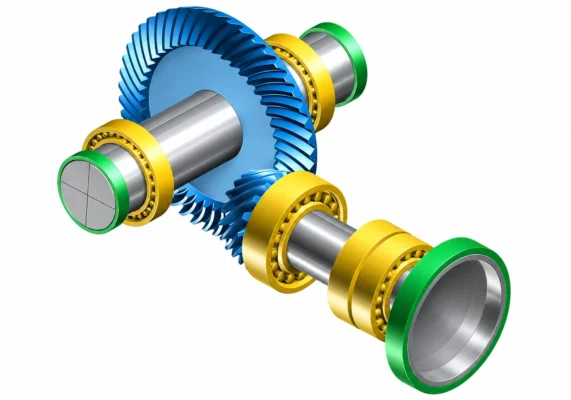
A bevel gear shaft rarely works alone. It operates with a mating gear, bearings and a housing. A part drawing describes the component, while an assembly drawing shows how it fits into the complete transmission.
The following information is useful:
Mating gear: Provide the mating gear drawing, tooth data or part identification. This is particularly important when the gear and pinion must operate as a matched pair.
Shaft angle and offset: State the required shaft angle and hypoid offset, if applicable. These values affect the gear geometry and assembly arrangement.
Mounting references: Identify the pinion mounting position, reference faces and bearing locations. These details help establish the intended gear position.
Bearing and housing arrangement: Include bearing positions, support dimensions, housing references and available installation space.
Operating conditions: Provide torque, speed, rotation direction, load and duty cycle. These factors help determine the required strength and inspection scope.
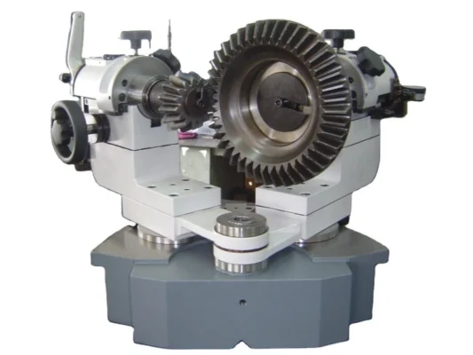
For some bevel gear projects, individual dimensional inspection is not enough. If the final acceptance depends on how the gear and pinion mesh together, matched-set inspection may also be required.
Read our article on when a bevel gear pair should be inspected as a matched set.
Which Material and Heat Treatment Details Should Be Specified?
Material selection depends on transmitted torque, operating speed, impact loads, wear and expected service life.
If the material has already been selected, provide the exact grade and applicable specification. If it is still open, share the application and operating conditions so the manufacturer can review suitable options.
Heat-treatment requirements may include:
- Carburizing, induction hardening, nitriding or another specified process
- Surface hardness
- Core hardness, where applicable
- Effective case depth for case-hardened components
- Hardness testing locations and acceptance criteria
- Post-treatment grinding or finishing requirements
Heat treatment can change shaft dimensions and gear geometry through distortion. Critical dimensions, machining allowances and finishing operations should therefore be considered before production.
A hardness value alone may not define the complete requirement. For case-hardened components, effective case depth and core properties may also need to be specified.
The manufacturing sequence matters as well. Turning, gear cutting, heat treatment, grinding and final inspection need to be planned around the part’s geometry and functional requirements.
Our article on how bevel gears are made and what affects quality provides further manufacturing context.
How Can Buyers Check Gear Accuracy and Quality?
Not every dimension needs the same tolerance. Buyers should identify the features that directly affect assembly, gear meshing and shaft operation.
Typical inspection items include:
Critical shaft dimensions: Verify bearing seats, gear mounting sections, shoulders and other functional dimensions.
Runout: Check radial and axial runout relative to the specified datum references. This helps evaluate rotational accuracy.
Geometric relationships: Confirm coaxiality, perpendicularity or other specified relationships between functional surfaces.
Gear accuracy: State the applicable accuracy standard and grade when these have been defined by the design.
Backlash and contact pattern: Define these requirements when inspection of the assembled gear pair is needed. They should be checked under an agreed mounting condition.
Material and heat treatment: Specify hardness, case depth and other required inspection records.
A general statement such as “high precision” is not an effective acceptance criterion. Drawings should identify measurable tolerances, and the RFQ should state which inspection reports are required.
For bevel gear projects, individual gear inspection and matched-pair inspection should be clearly distinguished. The inspection scope should reflect the actual function of the component.
What Should Buyers Include in a Custom Bevel Gear Shaft RFQ?
A complete RFQ does not need to include every engineering calculation. It should provide enough information for the manufacturer to understand the component, application and quality requirements.
| RFQ item | Information to provide |
| Drawing | Current 2D drawing and revision number |
| 3D model | STEP or IGES file, if available |
| Gear data | Gear type, tooth count, ratio and mating information |
| Shaft dimensions | Overall length, section diameters and bearing seats |
| Assembly | Shaft angle, mounting references and housing details |
| Operating conditions | Torque, speed, load and duty cycle |
| Material | Required grade or application conditions |
| Heat treatment | Process, hardness and case-depth requirements |
| Inspection | Critical tolerances, gear accuracy and required reports |
| Order details | Prototype quantity, annual demand and delivery destination |
If no drawing is available, buyers can start with a physical sample, clear photographs, mating components and application details. However, worn samples may not retain the original tooth geometry or shaft dimensions. Measurements should therefore be reviewed before they become production specifications.
For additional guidance on preparing bevel gear project information, see How to Prepare for a Bevel Gear Quote.
If your drawing is incomplete, you can still send the available information to Wenlio for an initial review. Missing parameters can be identified before the quotation and manufacturing route are finalized.
FAQ
Can a custom bevel gear shaft be manufactured from a sample?
Yes. A physical sample can provide a starting point for technical review. Mating components, assembly information and measurements are also useful, especially when the original part is worn or the drawing is unavailable.
What is the difference between an integral bevel pinion shaft and a separate gear assembly?
An integral bevel pinion shaft combines the pinion and shaft into one component. A separate assembly uses an independently manufactured bevel gear mounted onto a shaft through a specified connection, such as a spline or key.
Does every bevel gear shaft require carburizing?
No. Heat treatment depends on the material, load, wear and fatigue requirements. Carburizing, induction hardening, nitriding or other processes should be selected according to the approved design and application.
Why are shaft runout and bearing journal tolerances important?
They affect rotational accuracy, bearing fit and gear positioning. Excessive deviation may cause alignment problems and influence the contact condition of the mating gears.
Should buyers provide the mating bevel gear drawing?
Yes, whenever possible. The mating gear helps clarify tooth geometry, mounting relationships, backlash and contact requirements. It is particularly useful when the project involves replacement parts or matched gear sets.
Conclusion
A custom bevel gear shaft requires more than a gear profile and a few shaft dimensions. Gear geometry, bearing positions, mounting references, material, heat treatment and inspection criteria must be considered together.
For OEM buyers, providing clear drawings and assembly information helps reduce uncertainty during quotation, sampling and production. As a custom gear supplier, Wenlio supports custom bevel gear and shaft projects through drawing review, manufacturing feasibility assessment and agreed inspection requirements.
If you are developing a transmission component or sourcing a replacement bevel gear shaft, Contact Wenlio with your drawings, samples or application details to discuss your project.
