
Blogs, Bevel Gear
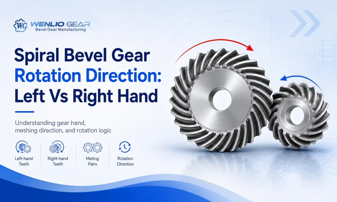
Spiral bevel gear rotation direction: left vs right hand
Aug
Introduction
Left-hand, right-hand, clockwise, and counterclockwise often appear on the same spiral bevel gear drawing. They are connected, but they describe different aspects of the gear set.
For spiral bevel gears, spiral hand refers to the direction of the tooth line, while rotation direction tells you how the gear turns in operation.
In Wenlio bevel gear projects, these details are reviewed together with the driving member, mating gear, shaft layout, viewing direction, and bearing arrangement to understand how the complete gear set will operate.
How does spiral bevel gear rotation direction work?
Left-hand and right-hand describe tooth geometry. They do not tell you whether the gear must rotate clockwise or counterclockwise.
A typical external spiral bevel gear pair has opposite spiral hands. Its operating rotation depends on which member drives the pair, how the shafts are installed, and which shaft end is used as the viewing reference.
This means that a right-hand spiral bevel gear is not automatically a clockwise-running gear.
What do left-hand and right-hand mean?
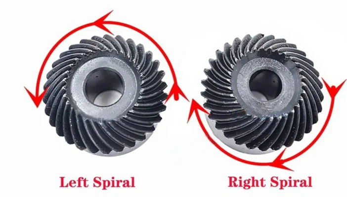
Spiral hand describes how the tooth line curves across the tooth surface.
How can you identify the spiral hand?
Under the common viewing convention, check the tooth-line curvature from the small end toward the large end of the gear. The direction of the curve identifies the gear as left-hand or right-hand.
The terminology is easier to understand when the two concepts remain separate:
- Spiral hand is a feature of the tooth geometry.
- Rotation direction is an operating condition.
Reversing the gear does not change its spiral hand. A right-hand gear remains right-hand in either direction of rotation.
Do mating spiral bevel gears need opposite hands?
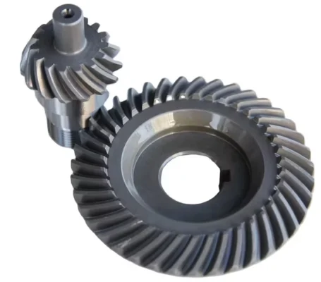
A pair of externally meshing spiral bevel gears normally uses opposite hands:
Right-hand pinion ↔ Left-hand gear or Left-hand pinion ↔ Right-hand gear
Why must the mating gear still be checked?
Correct hand does not guarantee a correct match.
When replacing a single spiral bevel gear, matching the tooth count, ratio, and outside diameter is not enough. The spiral hand and tooth geometry of the existing mating member also have to match the replacement.
For matched bevel gear sets, mounting position, backlash, and tooth contact are also part of the pairing review.
How is spiral bevel gear rotation direction determined?
Spiral hand alone cannot define clockwise or counterclockwise rotation.
To establish spiral bevel gear rotation direction, identify:
- The driving member;
- The driven member;
- The spiral hand of the pinion and gear;
- The shaft end used as the viewing reference;
- The installed position of each shaft.
Leaving out the viewing reference is a common source of confusion.
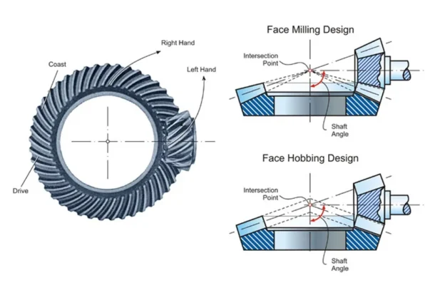
Why does the viewing direction matter?
A note such as:
Pinion rotates clockwise.
is still incomplete.
The same rotating shaft looks clockwise from one end and counterclockwise from the other. The drawing or specification should state the viewing position:
Pinion rotates clockwise when viewed from the input shaft end.
A rotation arrow and a defined viewing direction are usually clearer than writing only CW or CCW.
Does spiral hand affect axial thrust?
Spiral hand affects axial thrust, but it does not determine the thrust direction by itself.
As a spiral bevel gear transmits load, the tooth force has tangential, radial, and axial components. The direction of the axial component depends on:
- Spiral hand;
- Rotation direction;
- Whether the member is driving or driven;
- Spiral angle;
- Load direction.
For this reason, the bearing arrangement should be checked against the actual operating direction. The appearance of the teeth alone does not provide enough information.
This becomes more important when the transmission regularly switches between forward and reverse.
Why does rotation direction matter for replacement gears?
A worn gear sample can provide useful dimensions, but it rarely explains the complete operating relationship of the original pair. This is where spiral hand and rotation direction are often overlooked.
What can be missing from an old gear sample?
The sample will usually show the tooth count and some physical dimensions. It may not show:
- Which member originally drove the transmission;
- The normal direction of rotation;
- The spiral hand of the mating gear;
- Which shaft end defined CW or CCW;
- How the original gear pair was mounted;
- The original tooth contact condition.
As a result, a replacement may look similar to the old part but still be wrong for the transmission.
What should be provided for replacement?
Where possible, send:
- Photos of both the pinion and gear;
- Information about the mating member;
- Rotation arrows;
- The shaft angle;
- Installation or gearbox photos;
- Any available original drawings.
Together, these details show how the original pair was arranged and operated. That is more reliable than copying one worn component without its installation context.
Can left-hand and right-hand gears be interchanged?
Left-hand and right-hand gears are not normally direct substitutes.
Even if the tooth count and main dimensions appear similar, changing the spiral hand changes the tooth direction. Compatibility still depends on the geometry of the complete pair.
A proper check may include:
- Tooth count;
- Ratio;
- Spiral angle;
- Pressure angle;
- Shaft angle;
- Mounting distance;
- Backlash;
- Contact pattern.
Two gears having opposite hands does not mean they form a compatible pair. Their complete gear-set geometry must agree.
What should buyers confirm about spiral bevel gear rotation direction?
| Information | Why it matters |
| Pinion spiral hand | Identifies the tooth-line direction of the pinion |
| Gear spiral hand | Confirms the required mating hand |
| Driving member | Shows where power enters the gear set |
| Rotation direction | Defines how the set runs in operation |
| Viewing direction | Prevents CW / CCW confusion |
| Shaft angle | Confirms the transmission layout |
| Forward / reverse operation | Shows whether both directions carry load |
| Mating gear data | Supports a complete compatibility check |
How should rotation direction be shown on a drawing?
The clearest drawing note combines three pieces of information:
rotation arrow + viewing direction + driving member
For example:
Pinion: CW when viewed from the input shaft end.
For a bidirectional application, the drawing should also state that the gear set operates in both directions. If one direction carries the main load, identify that direction where relevant.
How does Wenlio review a spiral bevel gear pair?
Wenlio checks spiral hand and rotation direction within the complete gear-pair relationship rather than treating them as separate specifications.
The review covers:
- The left-hand or right-hand orientation of the pinion and gear;
- Which member drives and which member is driven;
- Rotation direction and its viewing reference;
- Shaft angle, ratio, and mounting conditions;
- Backlash and tooth contact requirements.
For drawing-based or sample-based custom gear projects, information about the mating gear and equipment installation can clarify the intended rotation relationship when the original documentation is incomplete.
FAQ
Does right-hand mean a spiral bevel gear rotates clockwise?
No. Right-hand describes the tooth-line direction. Clockwise describes the operating rotation. The driving member and viewing direction are also required to define rotation.
Do a spiral bevel gear and pinion have the same hand?
Usually, no. An external spiral bevel gear pair normally uses opposite hands, such as a right-hand pinion paired with a left-hand gear.
Does reversing rotation change the spiral hand?
No. Reversing the rotation does not change the spiral hand. However, the working tooth surface and axial force direction may change.
Can spiral bevel gears run in both directions?
Yes. In applications that frequently switch between forward and reverse, the review should also cover tooth contact on both flanks, backlash, axial thrust, and bearing support.
What should I provide for a replacement spiral bevel gear?
Provide photos of both the pinion and gear, tooth count, spiral hand, shaft angle, rotation direction, installation photos, and any available drawings. Mating gear information is particularly useful when checking compatibility.
Conclusion
Left-hand and right-hand describe the tooth-line direction of a spiral bevel gear. Clockwise and counterclockwise describe how it rotates in operation. To connect the two, you need to know the driving member, viewing direction, mating gear, and shaft layout.
For a new design or replacement project, include the spiral hand, rotation arrows, mating gear details, and installation information when you Contact Wenlio. This gives Wenlio the context needed to review the complete gear-pair relationship before manufacturing.
