
Blogs
What is a driving gear in a precision gear system?
Aug
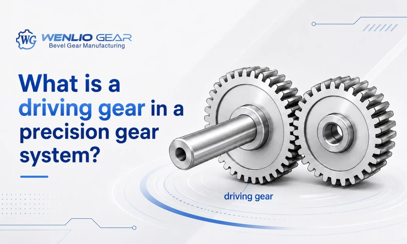
A driving gear is the gear that receives power in a specific gear mesh and transfers motion and torque to the mating gear. The term describes the gear’s role in the power path, not a separate type of gear. Spur, helical, bevel, and other gears can all act as the driver.
Introduction
Terms such as driving gear, driven gear, pinion, and input gear often appear together, but they do not mean the same thing. “Driving” and “driven” describe the direction of power through a particular mesh. Terms such as spur, helical, and bevel describe the gear geometry.
This difference becomes important when a gear needs to be designed, manufactured, or replaced. Identifying the driver helps establish the power path, but it does not provide a complete manufacturing specification. The mating gear, speed, torque, ratio, tooth geometry, material, heat treatment, and accuracy must still be reviewed together. A precision gear manufacturer will normally check these conditions before selecting the machining and inspection route.
What does a driving gear do?
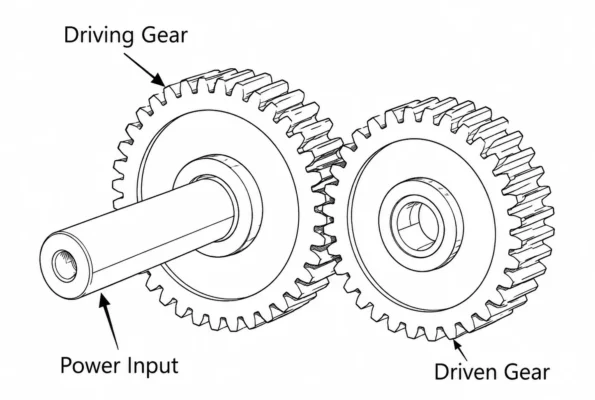
The driver receives power from a motor, shaft, or previous transmission stage and passes that power to the mating gear through tooth contact.
A simple power path looks like this:
Motor → Input Shaft → Driving Gear → Driven Gear → Output Shaft
Power flow determines the role.
The driver does not have to be the smaller gear or the gear with fewer teeth. Its name simply tells us which gear supplies power in that particular mesh.
Is a driving gear a specific type of gear?
No. “Driving gear” describes a function, not a gear type.
A simple way to separate the two terms is:
- Driving gear:the gear supplying power in a particular mesh
- Gear type:the tooth geometry and shaft arrangement
A spur gear may act as the driver in one machine, while a bevel gear performs the same function in another.
This is also why the term “driving gear” alone is not enough for manufacturing. Tooth data, dimensions, mating conditions, material, speed, load, and accuracy still need to be specified.
How can you identify the driving gear?
Follow the direction of power.
For a single gear pair:
Motor → Gear A → Gear B → Output
If the motor turns Gear A and Gear A transfers power to Gear B, Gear A is the driver and Gear B is the driven gear.
A multi-stage transmission makes this relationship even clearer:
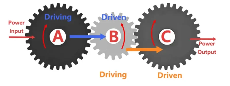
Motor → Gear A → Gear B → Gear C → Output
In the first mesh, Gear A drives Gear B. In the second mesh, Gear B may then drive Gear C.
Gear B therefore has two different roles. It is driven in the first stage and becomes the driver in the next. For this reason, driving and driven roles should be identified mesh by mesh rather than treated as permanent names for a component.
Which precision gears can act as driving gears?
Most common gear types can work as drivers. The required gear type depends on shaft arrangement, speed, load, available space, noise requirements, and transmission direction.
Spur gears
Spur gears are commonly used between parallel shafts. When a spur gear receives input power and transfers it to its mating gear, it acts as the driver in that mesh.
Their straight tooth geometry makes them common in reducers, agricultural machinery, industrial equipment, and automation systems.
Helical gears
Helical gears have angled teeth that engage more gradually than spur gear teeth. They are often used where smoother operation, higher speed, or lower noise is required.
The angled teeth also generate axial force during operation, so shaft and bearing support need to be considered when the gear carries load.
Bevel gears
Bevel gears transmit power between intersecting shafts, often arranged at 90 degrees.
When a bevel gear or pinion acts as the driver, the transmission setup also depends on the mating geometry, shaft angle, mounting position, backlash, and tooth contact.
Driving gear vs driven gear: what is the difference?
The difference comes from the direction of power in the current gear mesh.
| Item | Driving gear | Driven gear |
| Main role | Transfers power into the mesh | Receives power from the driver |
| Position in current mesh | Input side | Output side |
| Power source | Motor, shaft, or previous stage | Driving gear |
| Gear type | Spur, helical, bevel, etc. | Spur, helical, bevel, etc. |
| Size | Can be larger or smaller | Can be larger or smaller |
| Multi-stage gearbox | Role can change | Role can change |
One common mistake is to assume that the smaller gear must be the driver. Gear size alone does not determine power direction.
The same distinction applies to the term “pinion.” A pinion usually means the smaller gear, or the gear with fewer teeth in a pair. A driving gear is defined by power flow. A pinion can therefore be either the driver or the driven gear.
How do gear ratio, speed, and torque relate?
For a simple reduction gear pair:
Gear ratio = Driven gear teeth ÷ Driving gear teeth
For example:
- Driving gear: 20 teeth
- Driven gear: 40 teeth
- Gear ratio: 2:1
In this case, the driven gear rotates at approximately half the speed of the driver. In an ideal transmission, its torque increases by the same ratio. Actual output torque is slightly lower because the transmission has mechanical losses.
Gear ratio, however, does not define the complete gear geometry.
The same 2:1 ratio can be produced with different tooth counts, modules or diametral pitches, pitch diameters, and center distances. The available installation space and the actual tooth geometry still need to be confirmed before manufacturing.
Why does the driving gear matter in a precision gear system?
Two gears with similar dimensions can operate under very different conditions.
A gear that runs intermittently at low speed does not face the same demands as one that operates continuously at higher speed and load. These operating conditions can influence:
- Material selection
- Heat treatment
- Hardness and case depth
- Gear accuracy
- Tooth finishing
- Inspection requirements
Identifying the driver helps explain how power enters the mesh, but that is only one part of the technical review.
For manufacturing, the more useful questions are: What speed and torque will the gear carry? How long will it run? What operating conditions will it face?
Those details give the manufacturer a much clearer basis for selecting the process and inspection plan.
What information is needed before ordering?
For custom gears, a complete drawing is usually the best starting point. Before quotation or production, a custom gear supplier will normally need to confirm the following information:
| Information | Why it matters |
| 2D drawing / 3D model | Defines geometry, dimensions, tolerances, and datums |
| Gear type | Confirms spur, helical, bevel, or other geometry |
| Mating gear data | Shows how the two gears need to mesh |
| Speed and torque | Defines the operating load |
| Material / heat treatment | Affects strength and the manufacturing route |
| Accuracy requirement | Sets machining and inspection targets |
| Application / duty cycle | Explains how the gear will operate |
| Quantity | Affects process planning and production method |
Inspection requirements should also be agreed early. Depending on the drawing, these may include tooth thickness, runout, profile, lead, pitch, hardness, and other critical dimensions. When detailed measurement records are required, Wenlio’s guide on how to read a gear inspection report explains the common inspection items and how they are presented.
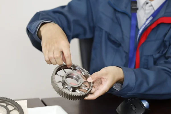
For replacement projects without complete drawings, an existing sample can also support the initial review. Photos, mating gear information, installation dimensions, and known wear conditions help establish what needs to be checked before a replacement part is produced.
What are common mistakes when ordering a driving gear?
Providing only the tooth count
Tooth count is only one part of the gear geometry.
Module or diametral pitch, pressure angle, tooth form, dimensions, tolerances, and mating gear information may also be required. Two gears with the same number of teeth can still have very different geometry.
Assuming the smaller gear is the driver
Gear size does not tell you which way power flows.
The most reliable way to identify the driver is to trace the power path from the motor, shaft, or previous transmission stage.
Providing only the gear ratio
A 2:1 ratio can come from many different tooth-count combinations.
The ratio alone does not define tooth size, center distance, strength, dimensions, or manufacturing accuracy.
Ignoring the mating gear
A gear never works by itself.
If the mating gear has different geometry, excessive wear, poor accuracy, or incorrect assembly conditions, a correctly manufactured replacement may still fail to mesh or operate as expected. The mating conditions should therefore be reviewed as part of the same project.
FAQ
Is a driving gear always the smaller gear?
No. The driving gear is defined by where power enters the gear mesh, not by its diameter or tooth count. It can be larger or smaller than the driven gear.
Is a driving gear the same as a pinion?
Not always. A pinion usually refers to the smaller gear or the gear with fewer teeth. A driving gear is the gear supplying power in a particular mesh.
Can a spur, helical, or bevel gear be a driving gear?
Yes. “Driving gear” describes a function rather than a gear type. Spur, helical, bevel, and other gear types can all act as drivers.
Does the driving gear alone determine the gear ratio?
No. Gear ratio depends on the relationship between the driving and driven gears, usually their tooth counts. One gear alone cannot define the ratio.
What information is needed for a custom driving gear quote?
A complete drawing is preferred, together with mating gear data, material, heat treatment, accuracy, speed, torque, and quantity. If no drawing is available, a sample and application information can support the initial review.
Conclusion
A driving gear is the gear that supplies power to another gear in a specific mesh. It may be a spur gear, helical gear, bevel gear, or another gear type. Its role depends on the direction of power flow, not its size or tooth form.
For manufacturing, identifying the driver is only the beginning. The mating gear, ratio, speed, torque, tooth geometry, material, heat treatment, accuracy, and inspection requirements still need to be reviewed together. If you are developing a new transmission or need a custom gear based on a drawing or sample, Contact Wenlio and send your technical information for an initial manufacturing review.
