
Blogs
How Can Common Gear Failure Modes Be Prevented
Sep
Gears operate under constant loads, repeated meshing, friction, and shifting temperatures. Over time, they can develop issues like pitting, wear, galling, cracks, and broken teeth. In high-speed and heavy-duty applications, a single gear failure can ripple through and disrupt the entire transmission system.
Gear failure is rarely caused by a single factor. Material selection and heat treatment define load capacity, gear geometry affects meshing behavior, installation quality influences tooth contact patterns, and lubrication, load, and working environment all affect the long-term condition of the tooth flanks. As a custom gear manufacturer, Wenlio focuses on understanding the full gear pair and real working conditions, not just the failed part itself. Knowing common failure modes helps technical teams locate problems faster and gives purchasing teams clearer standards for quoting, sample validation, and quality acceptance.
What Are the Common Gear Failure Modes?
Common failures may appear as pits, excessive wear, tooth root cracks, or broken teeth. Noise, vibration, and overheating are usually warning signals rather than failure modes themselves, because they can also result from backlash, bearings, installation, contact, or lubrication. The same symptom can have different causes, so diagnosis should be based on damage patterns and supporting inspection data rather than a single visible symptom.
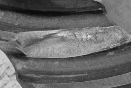
1. Tooth Root Fracture and Broken Teeth
Repeated bending loads can create fatigue cracks near the tooth root. Overload and impact are common causes, while the tooth root fillet, material, heat treatment, and machining quality can also increase risk. Heavy-duty applications should consider peak torque rather than average load alone.
2. Pitting and Spalling
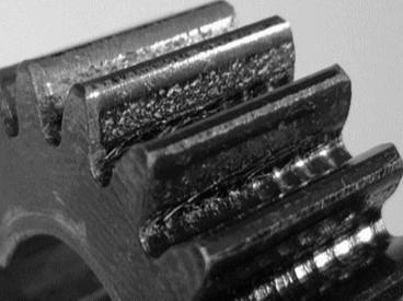
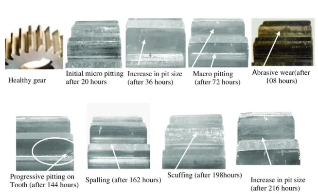
Pitting is contact fatigue caused by repeated tooth flank stress. Continued damage can develop into spalling. Besides hardness, contact pattern, heat treatment, surface quality, lubrication, installation, and load should be checked. For bevel and spiral bevel gears, concentrated edge contact can greatly increase local stress.
-774x400.webp)
3. Wear
Wear is the gradual loss of tooth flank material. Excessive or localized wear may result from poor lubrication, contaminated oil, abrasive particles, high surface roughness, or shaft misalignment. Record the location, direction, and depth of wear during inspection.
4. Galling and Scuffing
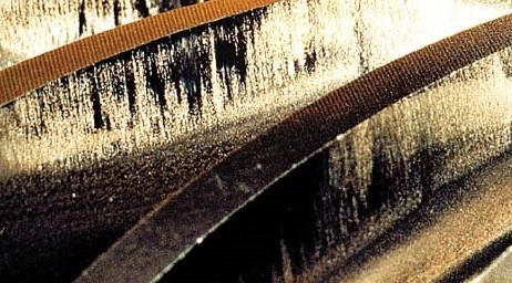
High sliding speed, load, and temperature can break down the lubricating film, causing adhesion, tearing, scratches, or material transfer. Lubricant type and viscosity, tooth flank temperature, surface roughness, and sliding conditions should be checked.
5. Plastic Deformation
Excessive tooth flank load can cause permanent deformation, including tooth tip deformation, material flow, or local indentations. Excessive load, insufficient hardness, and concentrated contact can change tooth profile and backlash.
6. Cracks
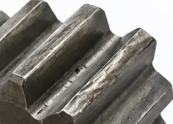
Cracks may occur at the tooth root, tooth flank, or gear body. They can be related to bending or contact fatigue, surface damage, material condition, or heat treatment. The crack origin and propagation should be investigated together with material and operating conditions.
7. Corrosion and Other Surface Damage
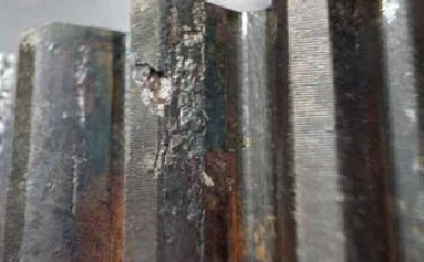
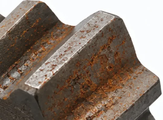
Moisture, contaminants, and inadequate rust prevention can damage tooth flanks and create local stress concentrations. Storage, packaging, rust prevention, and lubrication are important in humid or outdoor applications.
Quick Overview
| Common Failure | What Is Typically Observed? | Common Causes |
| Broken Teeth or Tooth Root Fracture | Cracks appear in the gear; in severe cases, an entire tooth breaks off | Overload, impact loads, excessive tooth root stress, material or heat treatment problems |
| Pitting or Spalling | Many small pits appear on the tooth flank; in severe cases, large areas of material detach | Excessive contact pressure, insufficient tooth flank hardness, uneven contact, insufficient lubrication |
| Abnormal Wear | The tooth flank becomes progressively thinner, with obvious wear marks or localized wear | Poor lubrication, contamination, misalignment during installation, tooth flank quality problems |
| Galling or Scuffing | Obvious scratches or scoring appear on the tooth flank, and material may even be removed | Excessive friction, excessive temperature, insufficient lubrication film, excessive load or sliding speed |
| Plastic Deformation | Indentations or deformation appear on the tooth flank or tooth tip, changing the tooth profile | Excessive load, insufficient material hardness, excessive local stress concentration |
| Cracks | Small or obvious cracks appear at the tooth root, on the tooth flank, or in the gear body | Long-term fatigue, stress concentration, material defects, heat treatment problems |
| Corrosion or Surface Damage | Rust, spots, or other surface damage appear on the tooth flank | Humid environment, contaminants, insufficient rust prevention, unsuitable lubrication conditions |
Why Do Gears Fail?
Although gear failures look different, their causes can generally be grouped into several areas.
Load Exceeds Design Conditions
Peak torque, impact, frequent starts and stops, and forward/reverse operation may differ from design assumptions. Long-term excessive loads increase tooth root and tooth flank fatigue risk.
Unsuitable Gear Geometry or Meshing Conditions
Module, tooth count, pressure angle, helix angle, tooth profile, and tooth lead affect meshing. Changes in center distance, backlash, mounting position, or contact pattern can change actual contact. Mounting distance is especially important for bevel gears.
Material and Heat Treatment Mismatch
Material strength, surface and core hardness, and effective hardened layer depth affect load capacity and wear resistance. A gear can meet drawing dimensions yet fail prematurely if material or heat treatment is unsuitable.
Manufacturing and Finishing Quality Problems
Tooth profile, tooth lead, spacing, runout, surface roughness, and heat treatment deformation affect final meshing. Review machining, heat treatment, finishing, and inspection records during failure analysis.
Installation and Shaft-System Changes
Bearings, shaft alignment, mounting distance, axial position, housing stiffness, and assembly adjustments can change tooth contact. Bevel gear pairs need contact confirmation after assembly even when individual parts meet their specifications.
Unsuitable Lubrication and Operating Environment
Lubricant type, viscosity, quantity, temperature, and cleanliness affect tooth flank condition. Dust, metal particles, and other contaminants can accelerate wear.
How Can the Root Cause of Gear Failure Be Determined?
After damage is discovered, record where it occurred and what it looks like. A practical investigation can follow these steps:
Step 1: Confirm the Failure Location
Record the affected gear, tooth flank area, and teeth involved. Check whether damage on multiple teeth follows a pattern.
Step 2: Observe the Damage Pattern
Distinguish pitting, spalling, wear, scratches, cracks, or fracture. Size, direction, and location can narrow the possible causes.
Step 3: Check Gear Pair Contact
Check backlash, contact pattern, mounting distance, and shaft alignment. Localized damage may indicate edge loading or uneven contact.
Step 4: Check Material and Heat Treatment
Confirm material grade, hardness, effective hardened layer depth, and heat treatment records.
Step 5: Check Actual Operating Conditions
Compare actual speed, torque, load changes, temperature, starts, and lubrication with design conditions.
Step 6: Review Inspection Records
Review tooth profile, tooth lead, spacing, runout, dimensions, and surface quality. Avoid judging the root cause from a damage photo alone.
How Can Gear Failure Be Prevented?
Gear failure prevention should cover design, manufacturing, assembly, and operation. Define actual load, speed, duty cycle, and service life, then select suitable geometry and material.
Manufacturing requires strict control over machining accuracy, heat treatment quality, and tooth flank finish. For assembly, be sure to verify shaft positioning, backlash, mounting distances, bearing condition, and contact patterns. Once in service, maintain proper lubrication practices and regularly monitor temperature, noise, vibration, and wear.
What Failure Risks Should You Watch for When Sourcing Gears?
For custom gear projects, many failure risks can be reduced during purchasing. At quotation and sample validation, clarify:
- Gear type and application
- Module, number of teeth, pressure angle, and helix angle
- Material grade and heat treatment
- Hardness and gear accuracy grade
- Backlash and contact pattern
- Mating gear information
- Surface roughness, critical dimensions, and tolerances
- Actual speed, torque, and load
- Inspection items and report requirements
For old gears or physical samples, provide the mating part, assembly relationship, and operating conditions when possible. A worn sample may not represent the original design. For volume production, first-article or sample validation should confirm dimensions, accuracy, material, heat treatment, and mating condition before production. This helps ensure that the replacement or custom gear matches the intended transmission condition rather than only matching the sample dimensions.
FAQ
What Are the Most Common Gear Failure Modes?
Common failures include broken teeth, pitting, wear, galling, plastic deformation, cracks, and corrosion. Causes depend on load, material, heat treatment, lubrication, and meshing.
Why Do Gears Fail Prematurely?
Common causes include overload, poor lubrication, accuracy problems, improper installation, shaft misalignment, and unsuitable material or heat treatment.
Does Gear Noise Mean the Gear Has Failed?
Not necessarily. Noise may also result from backlash, contact, bearings, installation, lubrication, or shaft alignment.
How Can Gear Failure Be Prevented?
Control design load, material and heat treatment, gear accuracy, contact, installation, and lubrication, with suitable inspection during production and assembly.
What Should You Check When a Gear Fails?
Start with the damage location and pattern, then check contact, backlash, material, hardness, lubrication, installation, load, and inspection records.
Conclusion
Gear failure can take many forms — broken teeth, surface pitting, excessive wear, galling, plastic deformation, cracking, or corrosion — and the root causes almost always build up over multiple stages rather than stemming from a single issue. Everything from load conditions and gear geometry to material selection, heat treatment quality, manufacturing accuracy, installation alignment, and lubrication plays a part in long-term gear performance. When running failure analysis, start with the actual damage pattern on the part, then work through supporting checks on gear-pair contact, material and heat treatment specs, manufacturing records, and real-world operating conditions.
For OEM builds and custom gear projects, defining clear key requirements up front — during quoting and sample validation — can significantly cut down on failure risks later on. If you’re troubleshooting a gear with wear, pitting, broken teeth, or other operational issues, or developing a custom gear project, you can Contact us to send drawings, samples, and operating condition information, we can evaluate your design, recommend manufacturing routes, and help establish the right inspection requirements.
