
Blogs
What Is Gear Pressure Angle? 14.5° vs 20° vs 25°
Sep
On gear drawings, pressure angle values such as 14.5°, 20°, and 25° often appear alongside module, tooth count, and other basic geometry. Although it looks like a simple angle, it affects the tooth profile, meshing behavior, tooth-root strength, and load direction within a gear pair.
Among modern involute gears, 20° is widely used as a standard pressure angle, while 14.5° is more common in older designs and 25° appears in applications where different strength and load characteristics are required. None of these angles is universally better; each reflects a different design balance. This guide from Wenlio explains how these differences affect real gear geometry and meshing.
What Is Gear Pressure Angle?
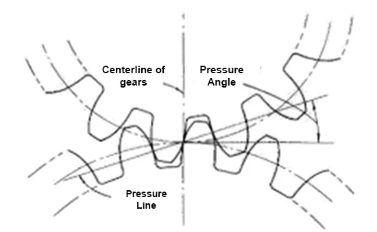
Gear pressure angle is an important geometric parameter that describes the direction of force transmission between involute gear teeth. For a standard involute spur gear, it can be understood as the angle between the line of action and the tangent to the pitch circle.
As the pressure angle changes, the base circle and involute tooth geometry also change. This is why pressure angle is not simply an annotation on a drawing—it is part of the geometry that determines how a gear pair engages and carries load. For a broader overview of these relationships, see our guide to gear design basics.
Key point:
Gears with the same module, tooth count, and outside diameter can still have different tooth profiles if their pressure angles are different.
How Does Gear Pressure Angle Affect Meshing?
During meshing, the force between two spur gear teeth acts along the line of action. This force can be resolved into a tangential component that transmits torque and a radial component that acts along the line connecting the gear centers.
Changing the pressure angle therefore changes both the tooth geometry and the direction of the transmitted force. A larger angle generally produces a more robust tooth root, while a smaller angle can favor a higher contact ratio under comparable geometric conditions.
Main Effects of Pressure Angle
- Changes the involute tooth profile
- Influences tooth-root geometry
- Affects radial and tangential force distribution
- Influences contact ratio and meshing behavior
Pressure angle should therefore be considered as part of the overall gear design rather than evaluated as an isolated value.
14.5° vs 20° vs 25° Gear Pressure Angle
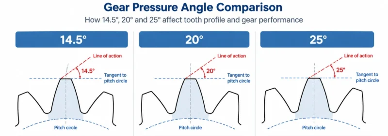
The differences between 14.5°, 20°, and 25° are easiest to understand by comparing their typical geometric and load characteristics.
| Pressure Angle | Main Characteristics | Common Effects |
| 14.5° | Smaller pressure angle | Usually offers a higher contact ratio, but has a relatively thinner tooth root and is more susceptible to undercutting at low tooth counts |
| 20° | Common modern standard | Offers a practical balance of tooth strength, contact characteristics, and manufacturing availability |
| 25° | Larger pressure angle | Usually gives a thicker tooth root, but also generates higher radial loading |
A 25° pressure angle should not automatically be considered an upgrade from 20°. The appropriate choice depends on the complete design, including tooth count, module, operating load, speed, support stiffness, and required meshing characteristics.
How Does Pressure Angle Affect Gear Tooth Strength?
Pressure angle influences tooth-root geometry. As the angle increases, the tooth root generally becomes thicker, which can improve resistance to bending stress.
It is also closely related to undercutting. In standard involute gears with a low tooth count, generating processes may remove part of the involute near the root. Smaller pressure angles are generally more susceptible to this limitation under comparable conditions.
Gear Strength Also Depends On
- Module
- Face width
- Material
- Heat treatment
- Surface hardness
- Tooth-root fillet
- Load cycles
- Tooth profile and lead accuracy
Pressure angle contributes to tooth strength, but it should never be used alone to judge the load capacity of a gear.
Does Gear Pressure Angle Affect Noise and Smoothness?
Pressure angle can influence meshing smoothness, but it does not determine gear noise by itself. Under otherwise similar conditions, a smaller pressure angle can provide a higher contact ratio, allowing load to be shared more continuously as one tooth pair leaves contact and another enters.
Actual noise and vibration, however, depend on the complete transmission system.
Common Factors Affecting Gear Noise
- Tooth profile and lead errors
- Surface roughness
- Speed and load
- Bearing and housing stiffness
- Installation accuracy
- Lubrication
- Material and heat treatment
For low-noise applications, pressure angle should therefore be evaluated together with gear accuracy, contact conditions, system stiffness, and operating speed.
How Does Gear Pressure Angle Affect Bearing Load?
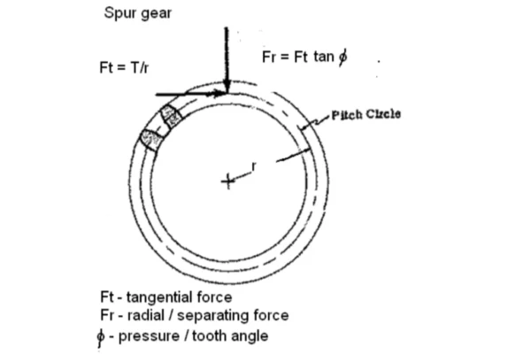
For a simple spur gear, the radial force can be approximated by:
Fr = Ft × tan φ
Where:
- Fr= radial force
- Ft= tangential force
- φ= pressure angle
With the same tangential force, increasing the pressure angle increases the radial force acting on the shafts and bearings. This means a change in pressure angle can also affect bearing selection, shaft deflection, and housing loads.
Design reminder:
Changing pressure angle should be treated as a system-level design decision, not simply as a way to modify tooth-root thickness.
Helical gears and bevel gears involve additional force components, so their load calculations require the corresponding gear geometry.
Can Gears With Different Pressure Angles Mesh?
Gears designed with different pressure angles should not be treated as interchangeable mating gears.
For example, a 20° gear and a 14.5° gear may share the same module and tooth count, but their base-circle geometry and involute profiles are different. They are therefore not designed to form the same conjugate tooth contact.
Being Able to Rotate ≠ Correct Meshing
A mismatched pair may sometimes assemble and rotate, yet still experience:
- Incorrect contact position
- Localized load concentration
- Increased noise
- Accelerated wear
- Premature surface damage
For this reason, pressure angle is one of the parameters that should be confirmed when identifying or reproducing an existing gear.
Pressure Angle in Spur, Helical and Bevel Gears
Pressure angle is used across different gear types, but its interpretation varies with gear geometry.
| Gear Type | Pressure Angle Key Points |
| Spur Gear | Pressure angle is defined directly in the transverse plane |
| Helical Gear | Normal and transverse pressure angles must be distinguished |
| Bevel Gear | Pressure angle must be considered together with pitch geometry, spiral angle, and tooth-surface geometry |
For helical gears, a drawing that simply states “20°” may require clarification as to whether it refers to the normal pressure angle or the transverse pressure angle.
For straight and spiral bevel gears, pressure angle forms part of a more complex three-dimensional geometry. It should therefore be interpreted together with other design parameters. Our guide to spiral bevel gear angles explains how pressure angle relates to spiral angle, shaft angle, and pitch cone angle.
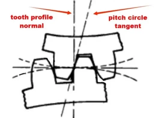
How Can You Identify a Gear’s Pressure Angle?
When a complete drawing is available, the pressure angle is usually specified directly. Identification becomes more difficult when only an old gear, sample, or incomplete technical information is available.
In practice, several measurements and geometric relationships may need to be considered together.
Common Reference Parameters
- Tooth count
- Module or diametral pitch
- Measurement over pins
- Measurement over teeth
- Tooth profile inspection results
- Base-circle geometry
- Mating gear information
- Center distance and meshing condition
If the gear is heavily worn, the original tooth geometry may already be altered. Visual inspection or outside-diameter measurement alone is therefore not a reliable way to distinguish, for example, a 14.5° gear from a 20° gear. When the module is also unknown, the methods in How to Calculate Gear Module can provide an additional reference for identifying the basic gear geometry.
Why Is 20° Pressure Angle So Common?
The widespread use of 20° is largely the result of its practical balance between tooth geometry, strength, and load characteristics.
Compared with 14.5°, it generally provides a stronger tooth-root form and reduces undercutting concerns at lower tooth counts. At the same time, it avoids some of the higher radial loading associated with larger pressure angles such as 25°.
Why 20° Became Widely Used
- Practical tooth-root geometry
- Better suitability for lower tooth counts than 14.5°
- Moderate radial loading
- High degree of standardization
- Broad tooling availability
- Wide industrial adoption
For an existing transmission, however, the original design specification remains the reference. A commonly used standard should not replace the pressure angle originally intended for the gear pair.
Common Misunderstandings About Gear Pressure Angle
Pressure angle is easy to oversimplify, especially when identifying or comparing existing gears.
| Common Statement | Correct? | Reason |
| 20° is suitable for all gears | No | It is common, but not universal |
| 25° is always better than 20° | No | It offers different strength and load characteristics |
| Gears with the same module can mesh properly | No | Tooth profile parameters must also be compatible |
| The same outside diameter means two gears are identical | No | Outside diameter does not define the complete involute geometry |
| A smaller pressure angle is always quieter | No | Noise depends on accuracy, structure, speed, load, and other factors |
The pressure angle is best understood as one part of the complete gear geometry rather than as a standalone performance indicator. More basic terminology and design references are available in the Wenlio Gear Guides.
FAQ
What is the most common gear pressure angle?
20° is widely used in modern industrial involute gears. However, 14.5° and 25° are still found in specific designs and applications.
Is a 25° pressure angle stronger than 20°?
A 25° pressure angle generally produces a thicker tooth root, which can improve bending strength, but it also increases radial loading. Its suitability depends on the overall design.
Can a 14.5° gear mesh with a 20° gear?
They should not be used as a normal mating pair. Their involute profiles and base-circle geometries are different even when module and tooth count are the same.
Does pressure angle change gear ratio?
Usually not. The theoretical gear ratio is primarily determined by the number of teeth, while pressure angle affects tooth geometry, contact conditions, and force transmission.
How do I know the pressure angle of an old gear?
If no drawing is available, pressure angle may need to be determined using tooth count, module or diametral pitch, measurements over pins or teeth, tooth profile inspection, and mating gear information.
Conclusion
Gear pressure angle is a basic geometric parameter with direct effects on tooth profile, meshing behavior, strength, and force transmission. The differences between 14.5°, 20°, and 25° are not simply a matter of one angle being better than another; each suits different design conditions and should be evaluated together with the rest of the gear geometry and operating requirements.
For existing gears, accurately identifying the original pressure angle is especially important when checking compatibility or reproducing a worn part. Wenlio focuses on bevel gears and precision transmission components. If you need to review gear drawings, identify an existing gear, or confirm bevel gear geometry and meshing requirements, Contact us with the relevant drawings or technical information.

Pingback: What Is Gear Contact Ratio and Why Does It Matter? - wenlio.com