
Blogs
Internal Gears: Types, Applications, and Manufacturing
Aug
Introduction
Internal gears have teeth on the inside of a ring and mesh with an external gear or pinion. Compared with common external gears, this arrangement supports more compact layouts, making internal gears a common choice for planetary gear systems, compact reducers, and other space-limited transmissions.
However, an internal gear is not simply a gear with teeth cut inside a bore. Tooth count, mating pinion geometry, tooth interference, material, heat treatment, tool access, and inspection requirements can all affect the manufacturing approach. In custom gear projects at Wenlio, internal gears are usually reviewed together with the mating gear and actual installation conditions.
What Is an Internal Gear?
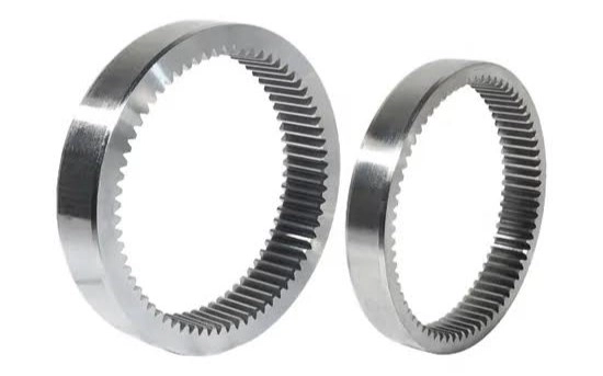
An internal gear has teeth on the inside diameter of a ring and usually meshes with an external pinion to transmit motion and torque.
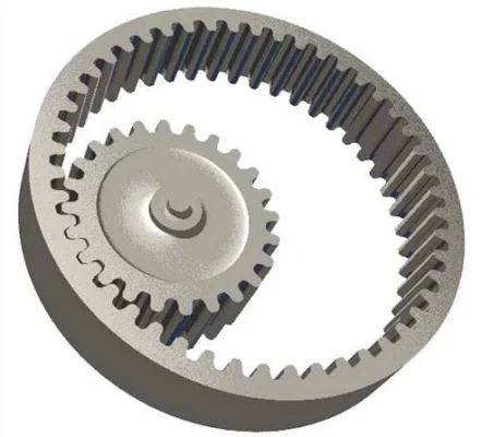
Unlike two external gears, which rotate in opposite directions, an internal gear and its mating pinion typically rotate in the same direction.
In planetary gear systems, the internal gear is commonly called an internal ring gear or ring gear. Actual tooth geometry and mating requirements should still be confirmed from the drawing.
What Are the Common Types of Internal Gears?
Internal Spur Gears
Internal spur gears have straight teeth parallel to the shaft axis and are one of the more common forms of internal gear.
They usually mesh with an external spur pinion and may be used in:
- Planetary gear systems;
- Compact reducers;
- Industrial machinery;
- Other internal-mesh drives.
For these projects, module, pressure angle, tooth count, face width, and mating pinion geometry should be confirmed.
Internal Helical Gears
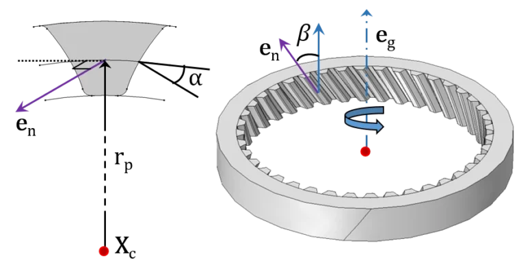
Internal helical gears use angled teeth, allowing more progressive tooth engagement.
Typical design parameters include:
- Helix angle;
- Helix hand;
- Normal module;
- Pressure angle;
- Axial load;
- Mating gear geometry.
As with external helical gears, the angled tooth form also creates axial force, so the bearing arrangement should be matched to the actual gear geometry.
Internal Gear vs External Gear: What Is the Difference?
| Factor | Internal Gear | External Gear |
| Tooth position | Inside the ring | Outside the gear body |
| Typical mating gear | External pinion | External gear |
| Rotation in mesh | Usually same direction | Opposite direction |
| Common use | Planetary and compact drives | General gear drives |
| Tool access | More restricted | More open |
| Typical cutting methods | Shaping or other internal cutting methods | Hobbing, shaping, milling |
Both can transmit motion and torque, but internal gears usually involve more restricted machining access and different inspection requirements because the tooth surfaces are inside the component.
Where Are Internal Gears Used?
Internal gears are useful in systems that require compact layouts or internal meshing.
Planetary Gear Systems
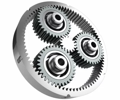
Planetary gear systems are one of the most common applications for internal gears.
A basic planetary gear set usually includes:
- Sun gear;
- Planet gears;
- Planet carrier;
- Internal ring gear.
In a properly designed planetary system, multiple planet gears can participate in load transmission, while the ring gear surrounds the planet gears and helps create a compact transmission arrangement within limited space.
Compact Reducers and Industrial Drives
Some compact reducers and industrial drive assemblies also use internal gears to meet space, ratio, or shaft-layout requirements.
These projects typically need to consider:
- Torque;
- Speed;
- Gear ratio;
- Available space;
- Bearing arrangement;
- Lubrication
Whether an internal gear is suitable depends on the complete transmission layout rather than the gear alone.
Machinery and Motion Systems
Internal gears also work in construction machinery, automation equipment, and other mechanical systems that use internal meshing or planetary stages.
For custom projects, review the mating gear, tooth-count relationship, and installation dimensions together during drawing review.
Why Are Internal Gears Useful in Planetary Systems?
An internal ring gear can surround the sun gear and multiple planet gears, making it especially useful in compact planetary gear systems. At the same time, under suitable design conditions, multiple planet gears can share the load. As a result, different relationships between the sun, ring, and carrier can provide different speed and torque characteristics.
However, the performance of a planetary system is not determined by the ring gear alone. Other factors also need to be considered:
- Sun gear;
- Planet gears;
- Tooth-count relationship;
- Center distance;
- Carrier geometry;
- Backlash;
- Gear accuracy.
For this reason, the internal ring gear should be reviewed as part of the complete gear relationship rather than as an isolated component.
Why Are Internal Gears More Difficult to Manufacture?
The main manufacturing challenges of internal gears come from limited machining space, internal tooth geometry, and mating relationships.
Tool Access Is More Limited
The cutting tool must enter the inside of the ring, so tool size, movement, and clearance are more restricted.
For designs with a small internal diameter, large face width, or surrounding structural interference, manufacturing can become more difficult.
Tooth Interference Needs to Be Checked
The tooth-count relationship and geometry of an internal gear and mating pinion cannot be selected arbitrarily.
If the tooth count, pressure angle, or other geometry is unsuitable, tooth interference or assembly problems may occur. Therefore, review the internal gear and mating pinion together before finalizing the manufacturing method.
Inspection Can Require Different Methods
Because the tooth surfaces are internal, measurements that are easy to perform on external gears may require different equipment or inspection setups for internal gears.
Depending on the drawing, inspection may include:
- Tooth thickness;
- Runout;
- Pitch;
- Tooth profile;
- Critical diameters;
- Hardness
The final inspection scope should match the required accuracy and application.
How Are Internal Gears Manufactured?
The manufacturing method depends on internal diameter, tooth geometry, material, accuracy, and production quantity.
Gear Shaping
Gear shaping is one of the common methods for cutting internal gears.
During shaping, the cutter reciprocates inside the bore while maintaining the required generating relationship with the workpiece. As a result, it gradually forms the internal tooth profile.
Compared with conventional hobbing, which is mainly used for external gears, gear shaping can produce many internal tooth structures that cannot be reached from the outside.
For projects that need to compare different manufacturing routes, Wenlio’s gear manufacturing process comparison can also provide a broader reference.
Broaching for Selected Applications
For some internal gear designs with stable geometry and higher production quantities, broaching may also be considered.
Its suitability usually depends on:
- Production quantity;
- Gear size;
- Tooth geometry;
- Accuracy;
- Tooling cost.
Because dedicated broach tooling is required, it is not the default choice for every internal gear project.
What Happens After Tooth Cutting?
After tooth cutting, the project may also require:
- Heat treatment;
- Deburring;
- Finishing;
- Dimensional inspection;
- Gear inspection.
If the project requires heat treatment, consider distortion and final accuracy early in the process. In addition, internal gear manufacturing involves more than simply cutting the teeth. Therefore, the finished part must also meet the drawing requirements for dimensions, tooth geometry, and inspection results.
What Should Buyers Provide for a Custom Internal Gear Quote?
For this reason, a custom internal gear project usually requires more technical information than just the outside diameter and tooth count.
| Information | Why It Matters |
| Drawing / 3D model | Defines complete geometry |
| Module / DP | Defines tooth size |
| Tooth count | Defines internal gear geometry |
| Pressure angle | Required for the tooth form |
| Mating pinion data | Helps review mating geometry |
| Gear dimensions | Determines tool access and manufacturing space |
| Material | Affects machining and performance |
| Heat treatment | Defines hardness and later finishing |
| Accuracy requirement | Determines manufacturing and inspection |
| Quantity | Influences process and tooling decisions |
For internal helical gears, also provide the helix angle and helix hand. In addition, a complete drawing gives the best starting point for most custom internal gear projects. However, if some details are still open, a sample, mating gear data, or application information can still support an initial manufacturability review.
How Does Wenlio Review an Internal Gear Project?
For internal gear projects, Wenlio first reviews the gear geometry and mating relationship, then defines the manufacturing and inspection route based on the following:
- Drawing and geometry
Module, tooth count, pressure angle, face width, and critical dimensions. - Mating relationship
Mating pinion, ratio, and relevant installation conditions. - Manufacturing feasibility
Internal diameter, tool access, and a suitable tooth-cutting method. - Material and heat treatment
Material, hardness, and later finishing based on the drawing and application requirements. - Accuracy and inspection
Runout, tooth geometry, and other critical inspection requirements.
For custom gear projects, the manufacturing route should be selected according to the actual geometry, quantity, and accuracy requirements rather than applying the same process to every internal gear.
FAQ
What Is the Difference Between an Internal Gear and a Ring Gear?</h3>
An internal gear has teeth on the inside diameter. In planetary systems, this type is commonly called an internal ring gear or ring gear.
Do Internal Gears Rotate in the Same Direction as the Pinion?
Yes. In a typical internal mesh, the internal gear and external pinion usually rotate in the same direction.
Can Hobbing Produce Internal Gears?
Conventional hobbing is mainly used for external gears. Internal gears are more commonly produced by shaping or other internal cutting methods.
Why Do Planetary Gear Systems Use Internal Gears?
They allow the sun and planet gears to mesh within a compact arrangement, making them well suited to planetary systems.
What Information Is Needed to Manufacture an Internal Gear?
Provide the drawing, module, tooth count, pressure angle, mating pinion data, material, heat treatment, accuracy, and quantity. For internal helical gears, include helix angle and hand.
Conclusion
Internal gears place the tooth form on the inside of a ring, providing a compact internal-mesh arrangement for planetary systems, compact reducers, and other industrial transmissions. Compared with external gears, they usually require more attention to tool access, mating geometry, and inspection.
For a new custom project, a complete drawing, mating pinion data, material, accuracy requirements, and application information can help define a more suitable manufacturing route. These details can be submitted when you Contact Wenlio for a custom internal gear project review.

Pingback: When Should You Use Gear Shaping Instead of Hobbing? - Wenlio