

A bevel gear ratio is determined by the tooth counts of the driving and driven gears. For a simple bevel gear pair, divide the driven gear’s tooth count by the driving gear’s tooth count. A 90° shaft arrangement does not automatically mean a 1:1 ratio; the required ratio depends on the machine’s input and output speed.
For engineers and OEM buyers, the calculation is only the starting point. Tooth counts must also suit the gear geometry, shaft layout, load and mating conditions. At Wenlio, our work as a precision gear manufacturer and custom gear supplier starts with reviewing the complete transmission, not just the gear ratio.
What Does a Bevel Gear Ratio Tell You?
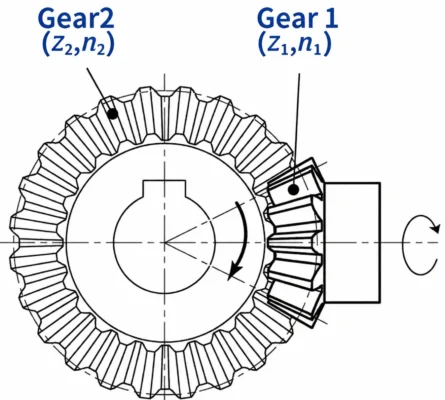
A bevel gear ratio describes the speed relationship between two meshing gears. The driving gear receives power from the input shaft, while the driven gear transfers motion to the output shaft. The ratio is based on their tooth counts.
Gear Ratio = Driven Gear Teeth ÷ Driving Gear Teeth
It can also be written as: i = z2 / z1
- i = Gear ratio
- z1 = Number of teeth on the driving gear
- z2 = Number of teeth on the driven gear
When the driven gear has more teeth, the pair reduces output speed. When it has fewer teeth, the output gear turns faster. Equal tooth counts give a 1:1 ratio.
The ratio describes the speed relationship. It does not define the full tooth geometry, gear size, load capacity or whether two gears will mesh correctly.
How to Calculate a Bevel Gear Ratio from Tooth Count
The calculation is simple once the driving and driven members have been identified correctly.
Step 1: Identify the Driving and Driven Gears
Trace the power flow through the transmission. The driving gear is connected to the input side of the mesh. The driven gear receives motion and transfers it to the output side.
Do not identify the driving gear by size alone. A pinion is often the smaller gear, but it is not automatically the driving member in every arrangement. Confirm the input and output sides from the assembly drawing or the machine.
Step 2: Confirm the Tooth Count of Both Gears
Find the tooth count for each gear from the approved drawing or verified gear data.
For a replacement project, do not rely only on a worn sample. Wear can affect measurement, and the mating gear may provide information needed to confirm the original design. If the tooth count is unknown, provide the sample, mating gear if available, clear photographs, key dimensions and application details for review.
Step 3: Divide the Driven Gear Tooth Count by the Driving Gear Tooth Count
Keep the order of the values clear: the driven gear tooth count is divided by the driving gear tooth count.
For example:
| Gear | Tooth Count |
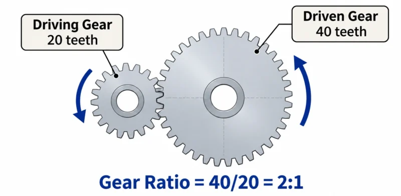
| Driving Pinion | 20 |
| Driven Gear | 40 |
40 ÷ 20 = 2
The gear ratio is therefore 2:1. The driven gear rotates at half the speed of the driving pinion. If the driving pinion turns at 1,500 rpm, the driven gear turns at 750 rpm in this single-stage example.
These values explain the calculation only. They are not a recommended design or a Wenlio product specification.
How Does the Gear Ratio Affect Output Speed and Torque?
The ratio helps determine the output speed. In a reduction arrangement, the driven gear has more teeth and rotates more slowly. In a speed-increasing arrangement, it has fewer teeth and rotates faster.
The ratio also affects torque. In an ideal gear pair, reducing speed increases output torque in proportion to the ratio. Actual output torque is lower due to mechanical losses and depends on the complete system.
Select the ratio from the machine’s requirements. Confirm the required output speed, input speed and transmitted load. A ratio that meets the speed target may still be unsuitable if the gear size, tooth geometry or load do not fit the application.
Does a 90° Drive Always Need a 1:1 Ratio?
No. The 90° description refers to the shaft arrangement, not the speed ratio.
A bevel gear pair can provide speed reduction, speed increase or 1:1 transmission, depending on the tooth counts. A miter gear pair has equal tooth counts and a 1:1 ratio. It is used when the drive needs to change the direction of power without changing speed through that gear stage.
If the machine needs a reduction or increase in speed, a different tooth-count relationship is required. The shaft angle and required ratio should therefore be confirmed as separate design requirements.
Also confirm whether the shafts intersect. Conventional bevel gears are used with intersecting shafts. If the shafts are offset, a hypoid arrangement may need to be considered.
What Other Factors Should You Check Beyond the Ratio?
A correct tooth-count ratio is necessary, but it is not enough to release a bevel gear pair for production. The ratio must work with the complete gear geometry and assembly conditions.
Gear Type and Shaft Arrangement
Confirm whether the design calls for straight bevel gears, spiral bevel gears or another arrangement. Tooth form affects how the pair engages and what manufacturing and inspection controls are needed.
The choice between straight bevel gears and spiral bevel gears should follow the application’s speed, load, noise requirements and existing gearbox design.
Tooth Geometry and Gear Size
Tooth count determines the basic ratio, but it does not define the complete gear. Module, pressure angle, pitch cone geometry and face width also matter.
Module relates to tooth size, not the ratio by itself. Two gear pairs can have the same ratio but different tooth counts and overall dimensions. The module of a bevel gear should therefore be checked with the other tooth data on the design drawing.
Mounting and Gear Pair Contact
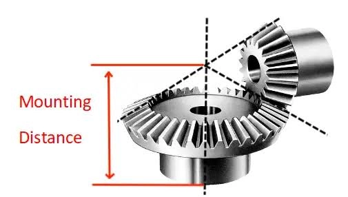
Bevel gears work as a pair. Their mounting positions, backlash and tooth contact affect how they mesh after assembly. A correct ratio cannot compensate for an incorrect mounting distance or incompatible mating geometry.
The bevel gear contact pattern should be reviewed under the specified inspection or assembly conditions. A shifted or edge-concentrated pattern may require a review of gear geometry, mounting position, backlash and mating components.
Load and Operating Conditions
Confirm the normal operating torque, expected peak load, speed range, duty cycle and direction of rotation. These details help determine whether the selected gear geometry and material suit the application.
The housing, bearings and lubrication should also be considered. A gear pair does not operate in isolation; its performance depends on the complete transmission system.
What Information Should You Confirm Before Manufacturing?
Before requesting a quotation or releasing a design, prepare the information needed to review the gear pair as a complete assembly.
| Information | Why It Matters |
| Driving and driven tooth counts | Confirms the basic ratio |
| Input and required output speed | Defines the transmission target |
| Shaft angle and arrangement | Confirms the gear layout |
| Gear drawings or CAD files | Defines tooth geometry and key dimensions |
| Mating gear information | Helps verify compatibility |
| Torque and working conditions | Supports design and material review |
| Material and heat treatment | Defines manufacturing requirements |
| Backlash and contact requirements | Clarifies assembly and inspection expectations |
| Quantity and application | Supports quotation and production planning |
If a complete drawing is not available, provide the existing gear, its mating part if possible, clear photographs, key dimensions and machine details. Missing design data should be confirmed before it becomes a production specification.
For OEM projects, state whether the gear is new or a replacement. A replacement must match the mating component and assembly conditions, not just the tooth-count ratio.
FAQ
Q1: How do you calculate a bevel gear ratio?
Divide the number of teeth on the driven gear by the number of teeth on the driving gear. Identify the input and output members correctly before calculating.
Q2: Does a 90° bevel gear drive have to use a 1:1 ratio?
No. A 90° drive describes the shaft arrangement. The ratio depends on the tooth counts. Equal tooth counts give a 1:1 ratio; different tooth counts provide speed reduction or increase.
Q3: What is the difference between a bevel gear ratio and a shaft angle?
The ratio describes the speed relationship between the driving and driven gears. The shaft angle describes the geometric relationship between the two shafts. They are separate design requirements.
Q4: Can two bevel gear pairs with the same ratio be interchangeable?
Not necessarily. The same ratio can be produced with different tooth counts and gear dimensions. Tooth geometry, module, pressure angle, mounting position and mating conditions must also be compatible.
Q5: What information should I send for a custom bevel gear quotation?
Send the gear drawings, tooth counts, target ratio, shaft arrangement, input speed, torque, mating gear data, material, heat treatment and quantity. If drawings are not available, provide samples, photographs and application details for an initial review.
Conclusion
Calculating a bevel gear ratio starts with the tooth counts of the driving and driven gears. The result establishes the speed relationship, but it does not confirm that the gear pair is suitable for the application. Shaft arrangement, tooth geometry, load, mounting position and mating conditions must also be reviewed.
Wenlio works with OEM customers on custom bevel gear projects, from drawing and sample review to manufacturing requirements and inspection planning. If you are developing a new right-angle drive or replacing an existing gear pair, send your drawing, sample details and application requirements through Contact Us for a project review.
