
Blogs
What Is Gear Contact Ratio and Why Does It Matter?
Sep
Two gears can rotate normally and still have less-than-ideal meshing conditions. Besides module, tooth count, pressure angle, center distance and tooth form, gear contact ratio is another important parameter for evaluating whether a gear pair can transmit motion continuously and smoothly.
In simple terms, contact ratio describes how many pairs of teeth are involved in transmitting load during meshing. It is influenced by tooth count, pressure angle, addendum, center distance, profile shift and, for helical gears, helix angle. At Wenlio, contact ratio is reviewed together with gear geometry, operating load, speed and installation conditions rather than treated as an isolated number.
What Is Gear Contact Ratio?
Gear contact ratio describes the average number of tooth pairs in contact during a meshing cycle.
For involute spur gears, the basic relationship is:
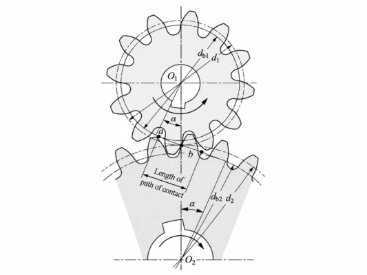
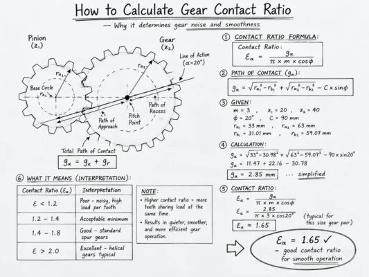
Contact Ratio = Length of Path of Contact ÷ Base Pitch
The path of contact is the distance over which one tooth pair remains engaged along the line of action. The base pitch is the spacing between corresponding points of adjacent involute teeth measured on the base circle.
For example, if a spur gear pair has a contact ratio of 1.6, it does not mean that exactly 1.6 tooth pairs are always touching. Instead, the mesh alternates between periods when one pair carries the load and periods when two pairs are in contact.
If the contact ratio falls below 1, the previous pair may leave before the next pair has fully entered mesh, which can interrupt continuous engagement. For conventional spur gears, this condition should generally be avoided.
For a broader explanation of module, pitch diameter, pressure angle and meshing geometry, see Gear Design Basics guide.
Why Does Gear Contact Ratio Matter?
Contact ratio matters because it affects how smoothly load passes from one tooth pair to the next.
When two pairs of teeth are engaged at the same time, part of the transmitted load can be shared between them. As one pair leaves the mesh, the next continues carrying torque. A suitable contact ratio therefore helps maintain continuity in power transmission.
It also affects mesh stiffness. During operation, the gear pair moves between single-pair and multiple-pair contact. Because the number of teeth carrying load changes, mesh stiffness also changes. This variation can influence transmission error, vibration and dynamic loading.
However, contact ratio should not be treated as a single performance score. Tooth profile accuracy, lead accuracy, alignment, backlash, surface finish and lubrication also affect actual gear behavior.
This is why the practical value of contact ratio is not simply that “more contact is better.” It is one of several geometric indicators used to evaluate whether a gear pair has a stable and suitable meshing condition.
What Factors Affect Gear Contact Ratio?
Several geometric parameters work together to determine the final contact ratio.
Pressure Angle
Pressure angle influences the length of the path of contact. Under otherwise similar conditions, a smaller pressure angle can provide a longer contact path and therefore a higher transverse contact ratio.
A larger pressure angle may provide a thicker tooth root, but it also changes radial loading and meshing geometry. This is why pressure angle should not be selected from contact ratio alone.
Tooth Count
Changing tooth count changes pitch diameter, base-circle diameter and the geometry of engagement.
A low tooth count, especially on the pinion, may also increase the risk of undercutting. Therefore, tooth numbers should not be selected only to achieve a required ratio. Contact ratio, interference and tooth-root geometry also need to be checked.
Addendum and Tooth Height
Increasing effective addendum can extend the path of contact and may increase contact ratio.
However, excessive addendum can produce thin tooth tips, increase sliding or create interference with the mating gear. The complete tooth form should therefore be checked rather than changing one dimension only to increase contact ratio.
Center Distance
Center distance changes the operating pressure angle and the actual meshing condition.
For involute gears, changing center distance does not destroy involute action, but it does change the working geometry. Contact ratio should therefore be checked using the actual operating center distance rather than only the nominal value.
Profile Shift
Profile shift is often used to improve low-tooth-count designs, reduce undercutting or adjust center distance. It also changes addendum proportions and engagement geometry.
Its effect on contact ratio depends on how positive and negative profile shifts are distributed between the pinion and gear. Profile shift should therefore be considered as part of the complete gear-pair design rather than as an independent adjustment.
How Does Contact Ratio Differ by Gear Type?
Different gear types develop tooth contact in different ways.
| Gear Type | Contact Characteristics | Main Consideration |
| Spur Gear | Teeth engage relatively directly | Mainly transverse contact ratio εα |
| Helical Gear | Teeth engage progressively across the face width | Transverse contact ratio εα + overlap ratio εβ |
| Spiral Bevel Gear | Contact develops along curved three-dimensional tooth surfaces | Tooth geometry, contact pattern and mounting conditions |
For helical gears, total contact ratio can be expressed as:
Total Contact Ratio εγ = εα + εβ
The additional overlap across the face width helps explain why helical gears generally engage more progressively than spur gears. However, the helix angle also creates axial thrust, so a higher overlap ratio cannot be considered independently from bearing and shaft design.
For a practical comparison, see Spur Gear vs Helical Gear: Which Fits Your Application?
Spiral bevel gears require a more complete evaluation because their tooth contact occurs on complex curved surfaces. Contact pattern and mounting position become particularly important.
What Is a Good Gear Contact Ratio?
There is no single ideal contact ratio for every gear application.
For conventional spur gears, a transverse contact ratio greater than 1 is a basic condition for continuous meshing. Beyond that, the correct target depends on the gear geometry and operating requirements.
A higher contact ratio can improve load sharing and meshing continuity, but maximizing it may create trade-offs. Increasing addendum may make the tooth tip thinner, changing pressure angle affects radial loading, and increasing helix angle may improve overlap while increasing axial load.
Gear accuracy and operating conditions must also be considered. A theoretically favorable contact ratio cannot compensate for significant profile errors, poor alignment or unsuitable backlash.
The better question is therefore not:
“How high can the contact ratio be?”
but:
“Is this contact ratio appropriate for the required load, speed, noise level, accuracy and installation conditions?”
Does Contact Ratio Affect Gear Noise?
Yes, but contact ratio is only one part of gear noise behavior.
As a gear pair moves between single-pair and multiple-pair contact, mesh stiffness changes. More continuous engagement can reduce abrupt changes in load transfer and may improve operating smoothness.
Actual gearbox noise also depends on tooth profile and lead deviations, microgeometry modifications, runout, backlash, surface finish, shaft alignment, bearings, housing stiffness, lubrication, speed and load.
This is why two gear sets with similar contact ratios can still produce very different noise levels in service.
If a gearbox becomes noisy, contact ratio should therefore be checked as part of the overall transmission system rather than treated as the only possible cause.
How Is Gear Contact Ratio Checked?
Contact ratio is primarily determined through gear geometry calculations or design software.
Manufacturing inspection does not directly “measure” the theoretical contact ratio. Instead, inspection verifies whether the finished gear matches the specified geometry. Contact-pattern or assembly checks can then help evaluate how the mating gears actually interact.
This distinction is important. A calculated contact ratio may be correct on the drawing, but the finished gear pair still needs to meet the required tooth geometry and assembly conditions before it can perform as intended.
In a real project, contact ratio should therefore be reviewed together with the drawing, mating gear information, speed, torque, accuracy requirements and installation conditions.
More related topics on gear geometry, inspection and meshing can be found in the Wenlio Gear Guides.
FAQ
What does a gear contact ratio of 1.5 mean?
It means the mesh alternates between one tooth pair and two tooth pairs in contact, with an average of about 1.5 tooth pairs participating during the meshing cycle.
Should gear contact ratio always be greater than 1?
For conventional spur gears, the transverse contact ratio should generally be greater than 1 to maintain continuous engagement. Other gear types may also rely on overlap contact.
Does a higher contact ratio make gears stronger?
Not necessarily. It can improve load sharing, but gear strength still depends on tooth geometry, material, heat treatment, face width, accuracy and operating load.
Why do helical gears usually engage more smoothly?
Helical teeth enter and leave contact progressively across the face width. This creates overlap in addition to transverse contact and makes the load transition more gradual.
Does contact ratio affect gear noise?
Yes, but it is only one factor. Gear noise is also affected by tooth accuracy, microgeometry, alignment, bearings, lubrication, speed and load.
Conclusion
Gear contact ratio describes how continuously gear teeth remain engaged during meshing. A suitable value supports stable load transfer and can influence mesh stiffness, vibration and operating smoothness. However, it should not be maximized without considering pressure angle, tooth geometry, center distance, strength and the rest of the transmission design.
In real gear projects, contact ratio should be reviewed together with the complete gear geometry, operating conditions and mating-gear information. If you need help reviewing the meshing conditions of an existing gear pair, Contact Wenlio with your drawings, mating gear data and application requirements for project review.
