
A worm gear and worm wheel must be designed to work together. Their module, pressure angle, lead geometry, number of starts, tooth count, center distance and backlash all affect how the two components mesh. If these details are not properly matched, the gear set may experience excessive friction, heat, noise or premature wear.
For OEM buyers and engineers, checking these details before ordering can help avoid problems during installation and operation. As a precision gear manufacturer and custom gear supplier, Wenlio understands the importance of matching gear geometry with material selection and manufacturing requirements. This article explains the main points to consider when selecting, replacing or ordering a custom worm gear set.
.jpg)
What Are the Worm Gear and Worm Wheel?
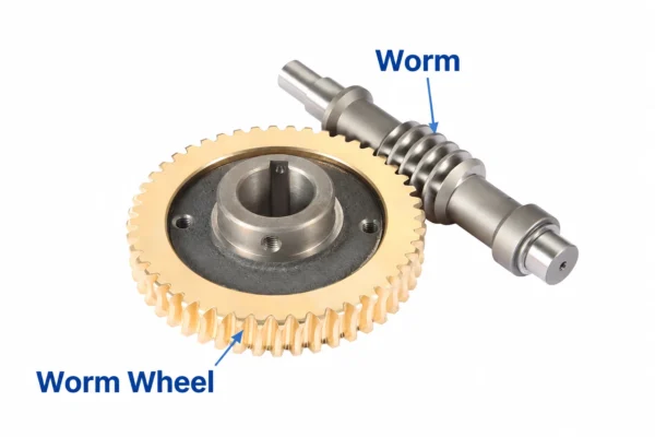
A worm gear set consists of two main components: a worm and a worm wheel.
The worm is a screw-shaped component with one or more threads. It usually acts as the driving part and transfers rotation to the worm wheel.
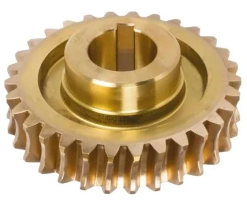
The worm wheel is the mating gear with specially designed teeth. It receives motion from the worm and provides the required output speed and torque.
These two components are commonly arranged with their shaft axes at approximately 90 degrees. This arrangement makes them suitable for compact right-angle transmission systems.
The transmission ratio depends on the number of worm starts and the number of teeth on the worm wheel.
For example:
- Worm: 1 start
- Worm wheel: 40 teeth
- Nominal transmission ratio: 40:1
A two-start worm and an 80-tooth worm wheel can also produce a 40:1 ratio. However, the two combinations are not automatically interchangeable because their lead geometry, dimensions and operating characteristics may differ.
If you are comparing different right-angle transmission solutions, read our guide to worm gear vs. bevel gear for more details.
Which Parameters Must Match in a Worm Gear and Worm Wheel Set?
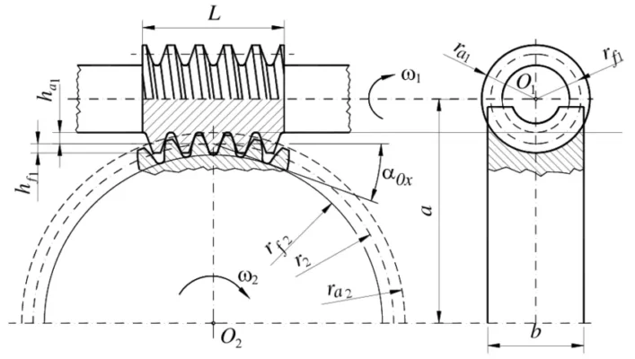
Several geometric parameters need to be checked before two components can be considered compatible.
| Parameter | What to Check | Why It Matters |
| Module and pitch | Compatible reference system | Determines tooth size and spacing |
| Pressure angle | Compatible tooth profile | Affects tooth contact |
| Worm starts and wheel teeth | Correct tooth count combination | Determines transmission ratio |
| Lead angle and hand | Compatible lead geometry and rotation direction | Affects meshing and movement |
| Center distance | Correct distance between shaft axes | Influences tooth engagement |
| Backlash | Suitable clearance between mating teeth | Helps control play and tightness |
Module and Pressure Angle
Module defines the basic size of gear teeth, while the pressure angle describes the geometry of the tooth profile.
However, worm gear calculations involve different reference systems, including axial, normal and transverse measurements. These values should not be treated as interchangeable.
In a common cylindrical worm gear system, the worm’s axial module corresponds to the worm wheel’s transverse module. The normal module is related to the lead angle.
Therefore, simply specifying the same module number is not enough. The reference system and tooth geometry must also be confirmed.
Pressure angle should follow the same design system to ensure the worm and wheel can form the intended contact.
When replacing an existing component, the original drawing is the best starting point for checking these specifications.
Number of Worm Starts and Wheel Teeth
The number of worm starts and worm wheel teeth determine the nominal transmission ratio.
The calculation is:
Transmission ratio = Worm wheel teeth ÷ Worm starts.
For example, a single-start worm driving a 40-tooth wheel produces a 40:1 ratio.
A two-start worm driving an 80-tooth wheel also produces a 40:1 ratio.
Although the ratios are the same, the two sets may have different lead angles, dimensions and operating characteristics.
For this reason, replacement parts should be selected according to the original gear design rather than the transmission ratio alone.
Lead Angle and Rotation Direction
The lead angle describes the inclination of the worm thread relative to its reference geometry. It influences sliding motion, transmission efficiency and the tendency of the output wheel to drive the worm backward.
The worm’s hand must also be confirmed. A right-hand worm and a left-hand worm have different thread directions and cannot be treated as interchangeable.
The required rotation direction and shaft arrangement should be checked before manufacturing.
This is particularly important for replacement projects where the original drawings may be incomplete.
Center Distance and Backlash
Center distance is the distance between the axes of the worm and worm wheel. It is an important part of the gear design and assembly arrangement.
If the center distance is too small, the teeth may mesh too tightly, increasing friction and operating temperature.
If it is too large, backlash may become excessive and the effective contact area may decrease.
Backlash is the clearance between mating tooth surfaces. It allows the components to move without excessive interference, but too much clearance can affect positioning accuracy and motion stability.
The required value depends on the application, load, operating temperature and assembly conditions. It should be specified and checked at the actual working center distance.
Do Material Selection and Lubrication Affect Worm Gear Performance?
Yes. Material pairing and lubrication are important because worm gear transmission involves considerable sliding contact between the tooth surfaces.
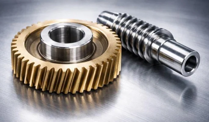
A common industrial combination is a hardened steel worm paired with a bronze worm wheel. The steel worm provides surface strength, while the bronze wheel offers suitable friction and wear characteristics for sliding contact.
Other material combinations may also be used depending on the application. The decision should consider:
- Transmitted load and operating speed
- Working temperature
- Duty cycle and operating time
- Required service life
- Lubrication method
Lubrication is equally important. Insufficient oil supply or an unsuitable lubricant can increase friction and temperature, leading to faster tooth wear.
The lubricant should be compatible with the selected materials and operating conditions. Material selection and lubrication should therefore be reviewed together during the design stage.
For a closer look at worm gear manufacturing quality, including material pairing, finishing methods and inspection requirements, see our related manufacturing article.
Can You Replace Only the Worm Wheel?
In some cases, replacing only the worm wheel is possible. However, the existing worm must be inspected before a replacement is ordered.
If the worm has severe wear, scoring or surface damage, installing a new wheel may not solve the original problem. The new component could continue running against a damaged contact surface.
Before replacing one component, check:
- Tooth surface wear, scoring and pitting
- Worm shaft runout and bearing condition
- Existing backlash and center distance
- Contact pattern after assembly
- Lubrication condition and possible metal particles
If both components show significant wear, replacing the matched pair may be a more reliable solution.
A single-component replacement is reasonable when the remaining part is still within its required condition and the original design allows separate replacement.
What Information Is Needed for a Custom Worm Gear Quote?
Providing complete technical information helps manufacturers review the design and avoid unnecessary changes during production.
A more accurate worm gear set quote depends on the technical details of both mating components, not just their outside dimensions.
For a custom or replacement worm gear project, buyers should prepare:
- Drawings or 3D files:Tooth geometry, shaft dimensions, bore and keyway details.
- Transmission ratio:Required ratio, worm starts and wheel teeth.
- Geometric specifications:Module or DP, pressure angle, lead angle, hand and center distance.
- Material requirements:Material specifications and heat-treatment requirements for both components.
- Operating conditions:Input speed, output torque, load, duty cycle and working temperature.
- Lubrication and backlash:Lubricant type and target backlash, if specified.
- Order quantity:Prototype, replacement or production quantities.
If the original drawing is unavailable, physical samples and clear photographs can help start the technical review. Assembly information is also useful because it provides additional details about the working arrangement.
The final specifications should be confirmed before production begins.
How Does Manufacturing Quality Affect the Final Gear Set?
Correct design parameters are only part of the process. Manufacturing accuracy also affects how the worm and wheel work together.
Tooth geometry, surface finish, heat-treatment consistency and dimensional inspection all influence the final contact condition.
For worm gear manufacturing, the production route depends on the component design and material. Typical operations may include turning, thread machining, heat treatment, grinding, worm wheel hobbing and dimensional inspection.
Important quality checks include:
- Tooth profile and lead accuracy
- Key dimensions and center distance
- Surface condition and hardness, where specified
- Shaft runout and concentricity
- Backlash and tooth contact after assembly
A complete gear inspection report helps buyers understand whether the manufactured components meet the agreed drawing and quality requirements.
For projects requiring drawing-based production, custom worm gear manufacturing also involves reviewing the geometry, material, machining route and inspection requirements before production.
At Wenlio, manufacturing requirements are reviewed against the customer’s drawings and application conditions. This helps ensure that the finished components meet the agreed technical specifications.
FAQ
Do a worm gear and worm wheel need the same module?
They need compatible module systems, but the reference measurements must be confirmed. For a common cylindrical worm gear system, the worm’s axial module corresponds to the worm wheel’s transverse module.
What determines the transmission ratio of a worm gear set?
The nominal ratio is calculated by dividing the number of worm wheel teeth by the number of worm starts.
Are all worm gear sets self-locking?
No. Self-locking depends on lead angle, friction and operating conditions. It should not be assumed without verification or used as a substitute for an independent braking system.
Can I replace a worm wheel without changing the worm?
Yes, in some applications. However, the existing worm must be in acceptable condition, and backlash and tooth contact should be checked after installation.
What information should I provide when ordering custom worm gears?
Provide drawings or samples, transmission ratio, module, pressure angle, lead angle, center distance, material, operating conditions and order quantity. These details help the manufacturer review the design before production.
Conclusion
A worm gear and worm wheel need to be evaluated through their complete geometry and operating conditions. Module, pressure angle, lead geometry, worm starts, wheel teeth, center distance and backlash determine whether the components can work together correctly. Material selection, lubrication and manufacturing accuracy also affect their service performance.
Wenlio supports custom gear projects through drawing review and manufacturing coordination. Whether you need replacement components or a new worm gear set, Contact Wenlio and share your drawings, samples or project requirements for a technical review.
