Gear Guides/Gear Inspection

Tooth Geometry Control

Tooth Profile Deviation: Causes, Measurement, and Control

Tooth profile deviation shows how the measured tooth flank differs from the specified profile through the evaluation range. It can reveal form error, slope error, an incorrect modification, or several conditions acting together.

For a useful decision, read the profile trace with the drawing, tolerance standard, heat-treatment condition, inspection setup, and mating-gear requirements.

Review Your Gear Drawing Explore Gear Guides
Analytical inspectionProfile Trace

Flank 01

ROOTTIP

SpecifiedMeasured
TotalFα
Formffα
SlopefHα
01

FαTotal profile deviation

Overall variation across the defined evaluation range.

02

ffαProfile form deviation

Local shape variation after the slope component is removed.

03

fHαProfile slope deviation

Overall inclination of the measured trace against the target.

Quick Definition

What Does Tooth Profile Deviation Actually Measure?

It is the difference between the measured tooth flank and the specified profile within a defined evaluation range.

For a standard involute gear, the reference is the nominal involute. If the drawing specifies tip relief, profile crowning, or another modification, that geometry becomes part of the target.

Profile deviation is not the same as pitch deviation, helix deviation, runout, tooth thickness, or surface roughness. Each item describes a different part of gear geometry and must be checked separately.

Three reference points

01

Specified profile

The nominal involute plus any approved profile modification.

02

Measured profile

The flank trace recorded by the selected analytical measuring system.

03

Evaluation range

The active section used to calculate and report profile values.

Scope: ISO 1328-1 covers flank tolerance classification for individual cylindrical involute gears. Bevel gears should follow the drawing, applicable standard, and agreed inspection method.

Inspection Report

Read the Trace Before You Judge the Number

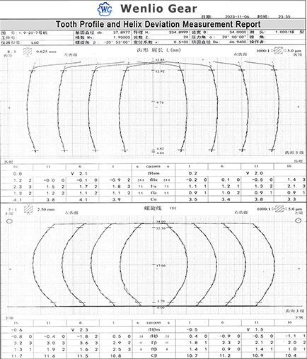
The reported value tells you whether a limit was exceeded. The trace helps show where and how the flank differs from the target. Both are needed for a practical manufacturing decision.

Report item What it describes Buyer check
FαTotal deviation Combined variation across the evaluation range. Grade, flank, range, and limit.
ffαForm deviation Local waviness or curvature after slope is removed. Irregular shape and process stability.
fHαSlope deviation Overall inclination relative to the target profile. Tip or root trend and specified relief.
Evaluation rangeActive section The profile interval included in the calculation. Same datum and range for approval.
ModificationDesign intent Tip relief, crowning, or other intentional geometry. Correct target loaded in the software.
Tooth Profile and Helix Deviation Measurement Report-wenlio
Example report

Report layouts vary by machine, standard, and inspection software. Confirm the evaluation settings before comparing results from different sources.

Functional Review

Why Profile Deviation Matters in the Finished Gear

A profile result matters because it changes how the tooth pair enters, carries, and leaves contact. Its actual effect depends on the mating gear, load, speed, alignment, lubrication, housing stiffness, and intentional microgeometry.

A passing profile value does not replace checks for pitch, helix, runout, tooth thickness, backlash, surface condition, and mounting accuracy.

01

Contact Distribution

An incorrect profile can move contact toward the tip, root, or a smaller portion of the active flank.

02

Transmission Error

Profile shape influences mesh stiffness and may contribute to vibration or tonal noise.

03

Local Tooth Stress

Concentrated contact can increase local pressure and affect wear or surface durability.

04

Assembly Behavior

The final contact pattern also depends on lead, backlash, alignment, bearings, and housing conditions.

Root Cause Map

What Can Cause Tooth Profile Deviation?

The trace shape is a clue, not proof of the root cause. Compare the report with tool condition, machine data, setup records, heat-treatment results, and repeat measurements.

A

Tool Condition

Hob geometry, cutter wear, sharpening error, wheel loading, and dressing variation can transfer to the flank.

Check: tool history and correction data

B

Machine and Setup

Synchronization, center distance, axis alignment, feed settings, thermal drift, and machine condition affect generation.

Check: setup sheet and machine trend

C

Workholding

Fixture runout, poor datum condition, unstable clamping, or part deflection can distort the measured result.

Check: datum and fixture runout

D

Heat Treatment

Residual stress, hardness variation, carburizing response, and quench distortion can move the profile after soft cutting.

Check: pre-process and post-process reports

E

Process Route

Uneven stock, insufficient allowance, or a route unable to correct distortion may leave the final profile outside tolerance.

Check: allowance and finishing capability

F

Measurement Setup

Wrong gear data, stylus, datum alignment, filtering, range, or modification settings can create a misleading report.

Check: inspection program and master data

Process Control

Control the Profile Before Final Inspection

Control begins with a clear drawing. Production and inspection teams should use the same gear data, tolerance system, profile modification, evaluation range, material condition, and acceptance method.

During manufacturing, connect measurement trends with tool life, setup condition, material lot, heat-treatment batch, finishing allowance, and machine corrections. Final inspection confirms the result, but it cannot replace process control.

Gear Grinding After Heat Treatment
01

INPUTDrawing Review

Confirm tooth data, standard, grade, modification, evaluation range, and report requirements.

02

ROUTEProcess Planning

Select cutting, heat treatment, allowance, and finishing operations that support the requirement.

03

CONTROLTool and Setup Management

Track tool condition, datum surfaces, fixture runout, machine settings, and correction history.

04

FEEDBACKIntermediate Measurement

Inspect while correction remains practical, especially before and after heat treatment.

05

RELEASEFinal Analytical Inspection

Verify profile, helix, pitch, runout, and agreed dimensional requirements before shipment.

RFQ Checklist

Give the Supplier a Measurable Target

A request such as “good tooth profile” cannot be quoted or inspected consistently. Provide the applicable standard, quality grade, modification, evaluation condition, material state, and required records.

✓2D drawing and available 3D model

✓Gear type, module or DP, tooth count

✓Pressure angle and reference system

✓Standard, quality grade, and limits

✓Profile modification and range

✓Material, hardness, and heat treatment

✓Mating gear and operating conditions

✓Quantity and inspection documents

01

Replacement gear projects

Do not assume wear represents the original geometry.

If the original profile specification is missing, share the mating gear, application, operating conditions, sample history, and any previous inspection report.

Custom Gears Made to Drawing or Sample

Buyer Questions

Tooth Profile Deviation FAQ

Five practical questions commonly raised during drawing review, quotation, and inspection approval.

No. Profile deviation describes the shape of one tooth flank through the evaluation range. Tooth thickness describes the distance between the two flanks and affects backlash and fit.

No. Noise also depends on pitch, helix, runout, surface condition, profile modification, contact ratio, mating parts, alignment, housing stiffness, load, speed, and lubrication.

Yes. Residual stress, case depth, part geometry, loading method, and quenching conditions can change tooth geometry. The route should allow for distortion and any required hard finishing.

Grinding can correct suitable hardened gears when enough allowance, tool access, machine capability, and stable reference surfaces are available. It cannot correct every design or distortion condition.

It should identify the part, gear data, measured flanks or teeth, evaluation method, profile traces, reported values, tolerance limits, and the agreed pass or fail result.

Drawing and Inspection Review

Need to Review a Tooth Profile Requirement?

Send your drawing, gear data, modification, material, heat treatment, quantity, mating-gear information, and required inspection records. Wenlio can review the specification and proposed manufacturing route before quotation.